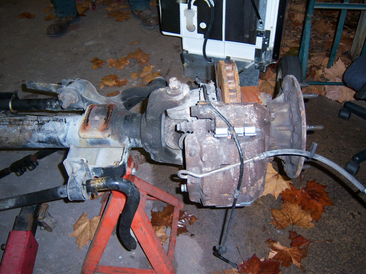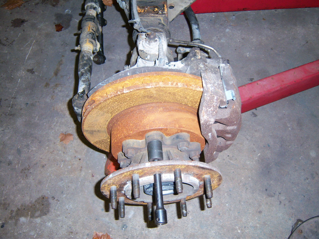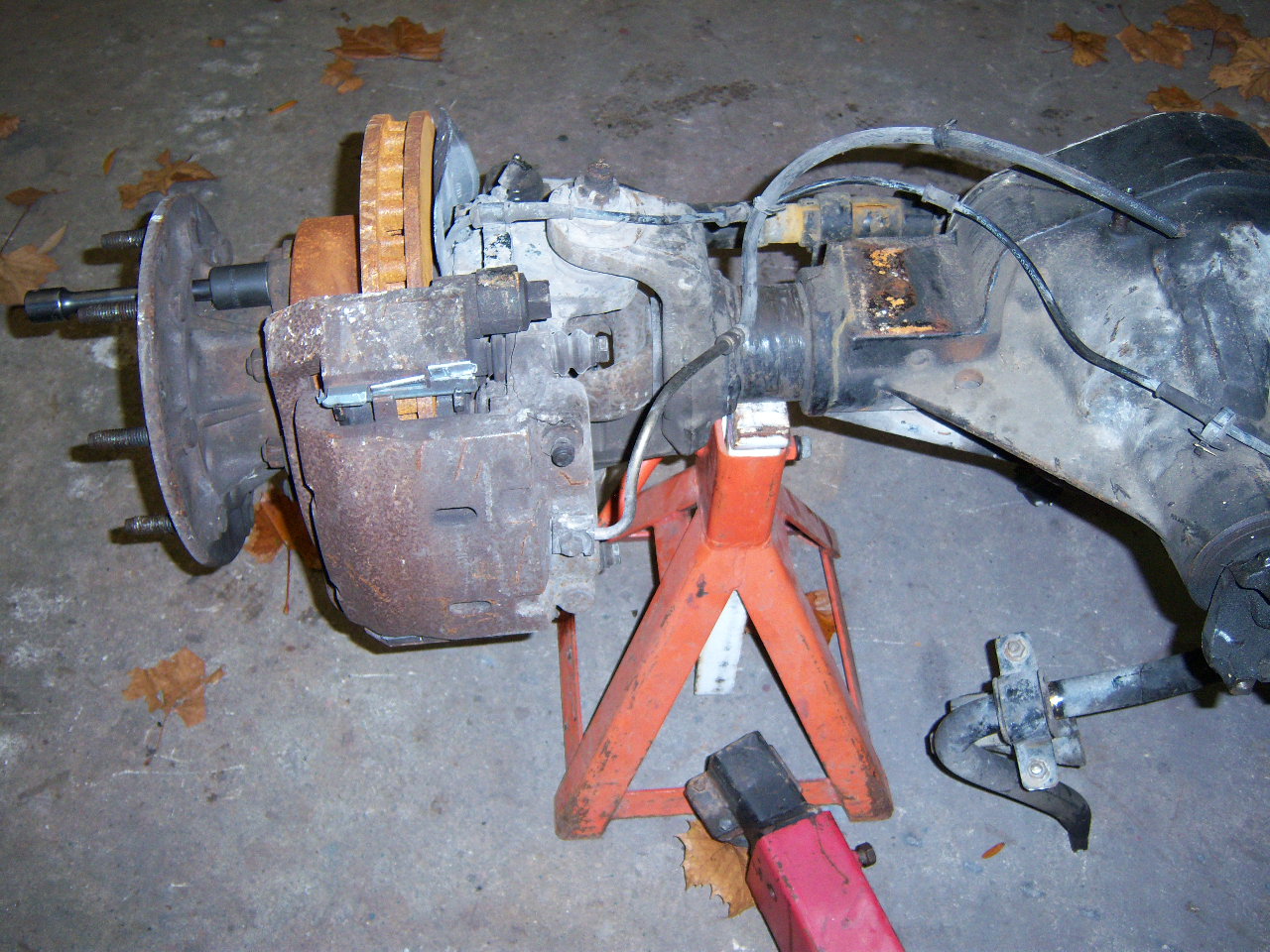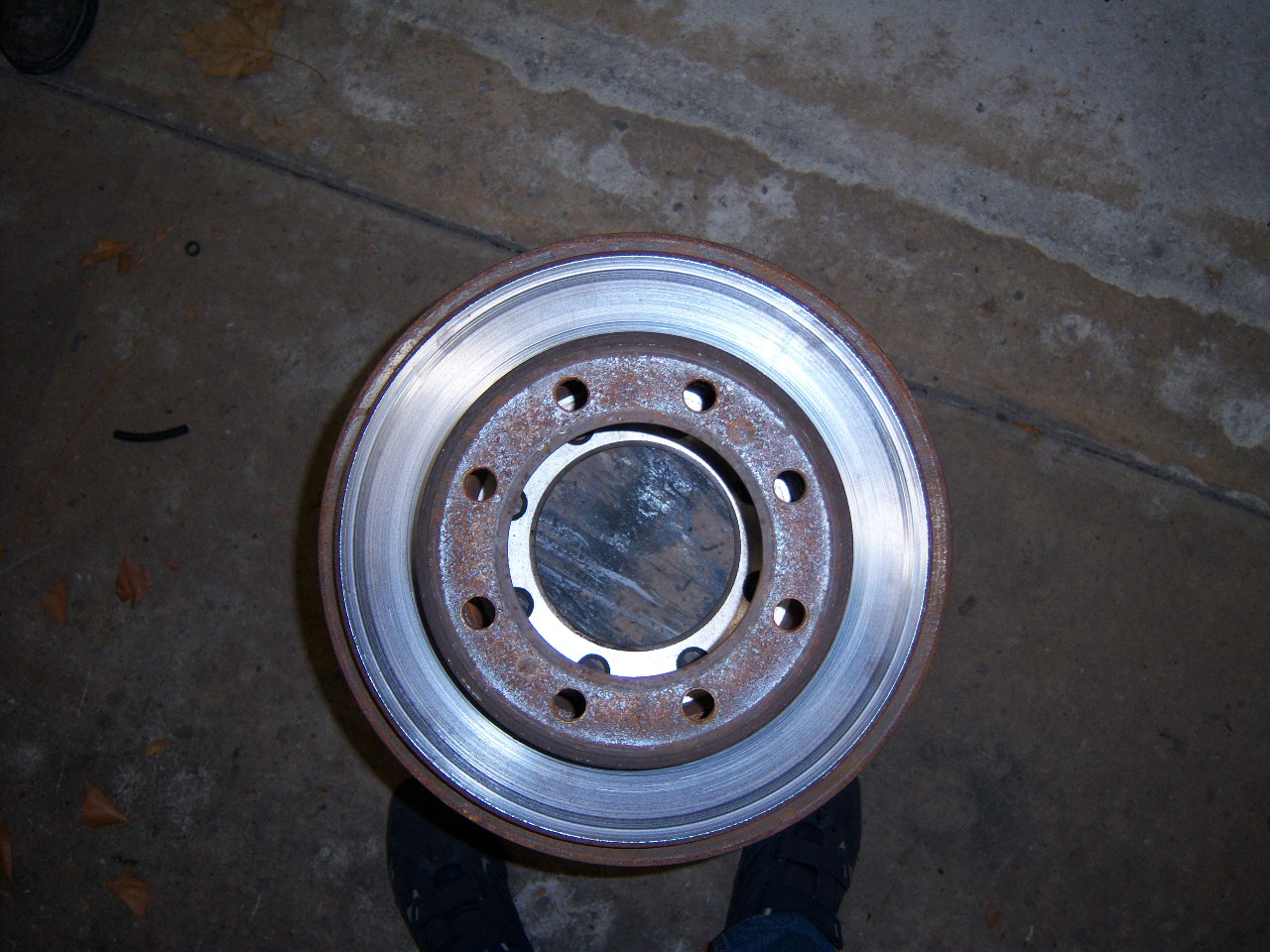
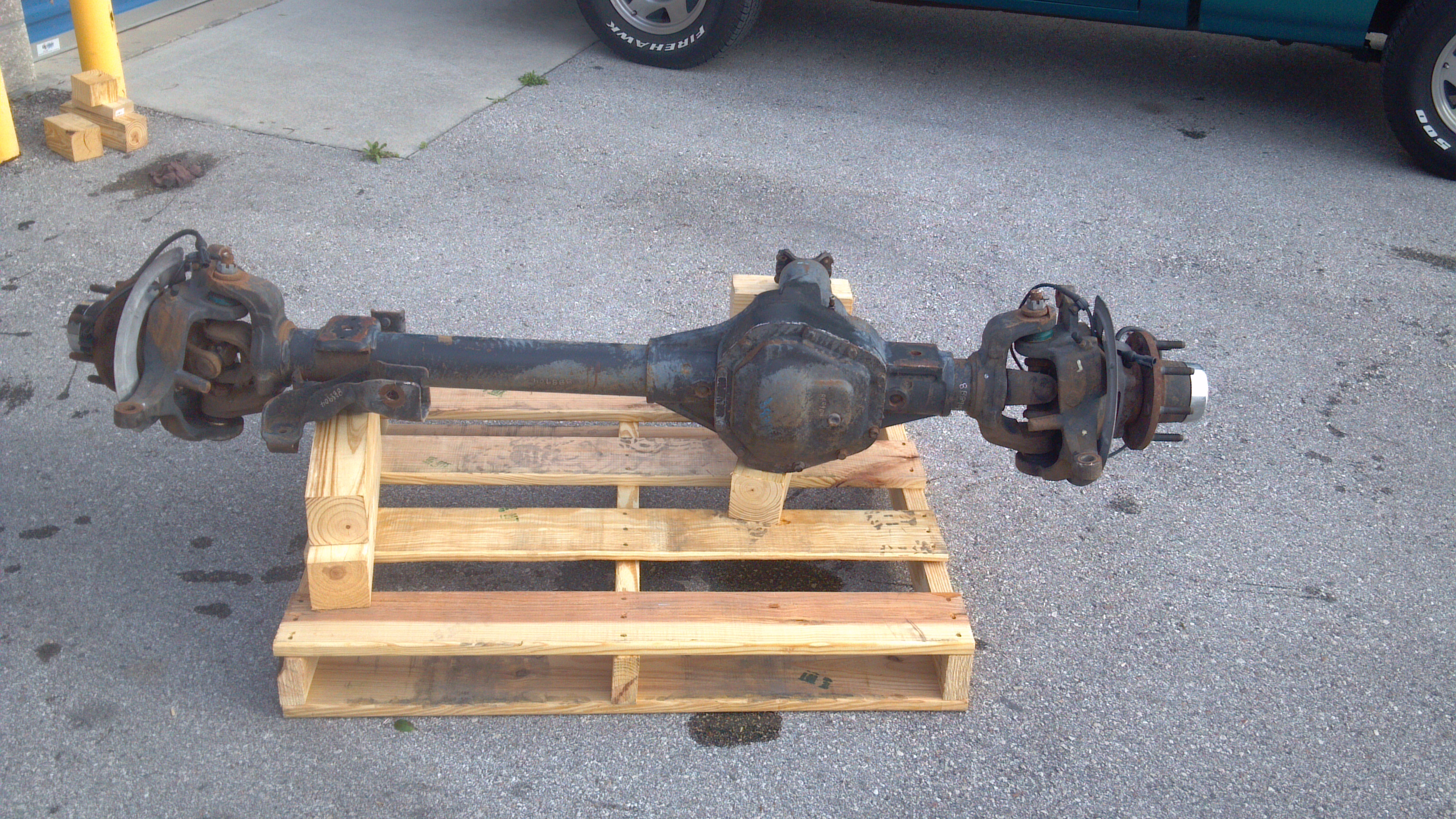
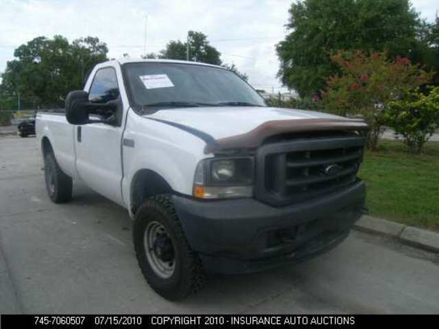
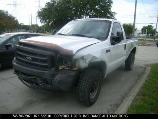
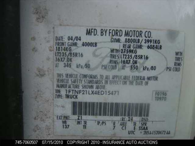
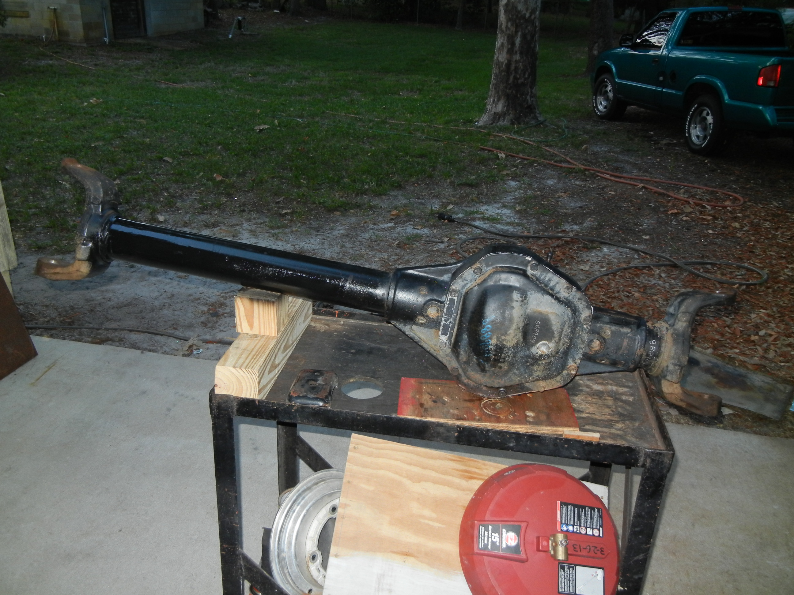
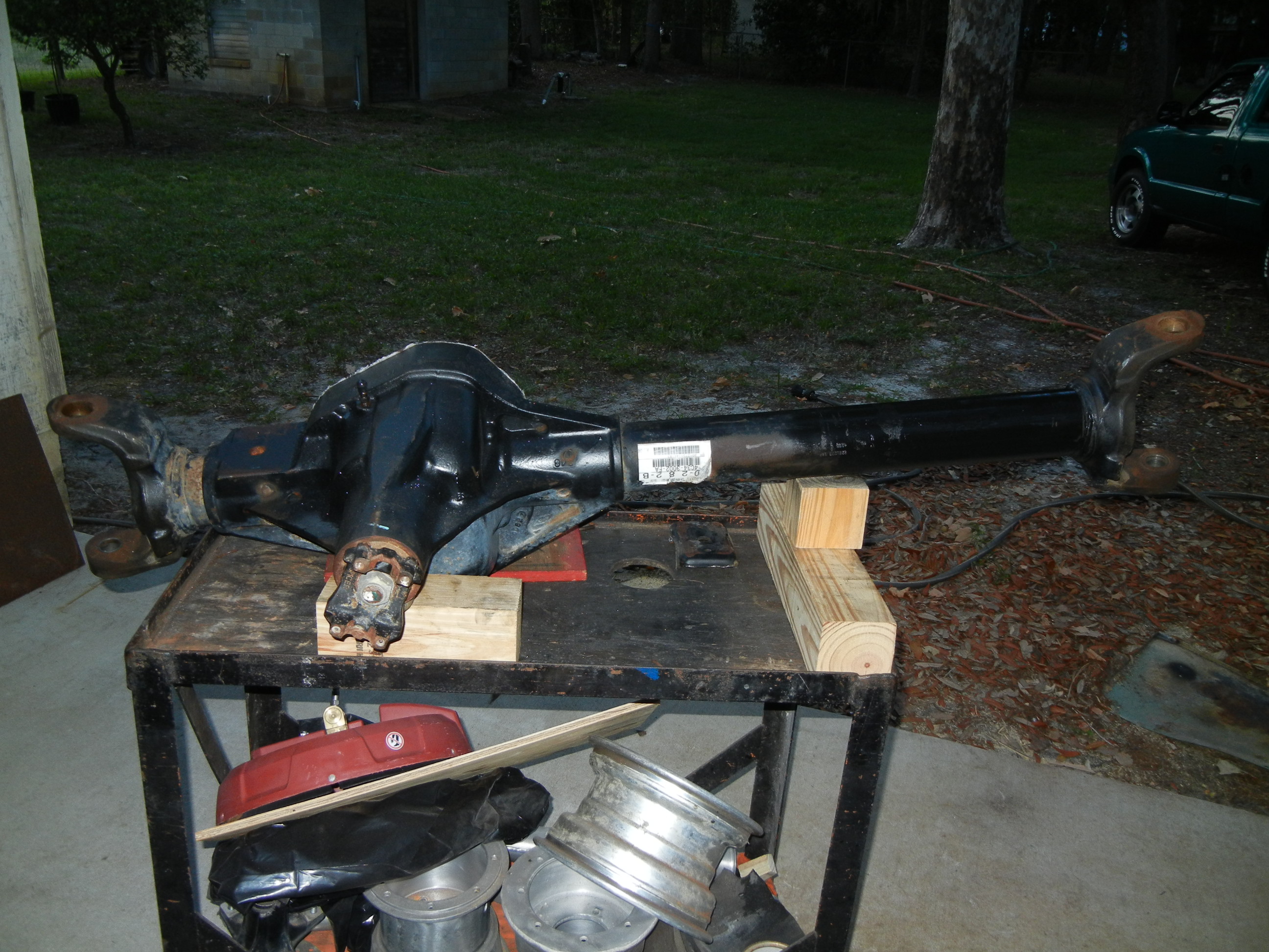
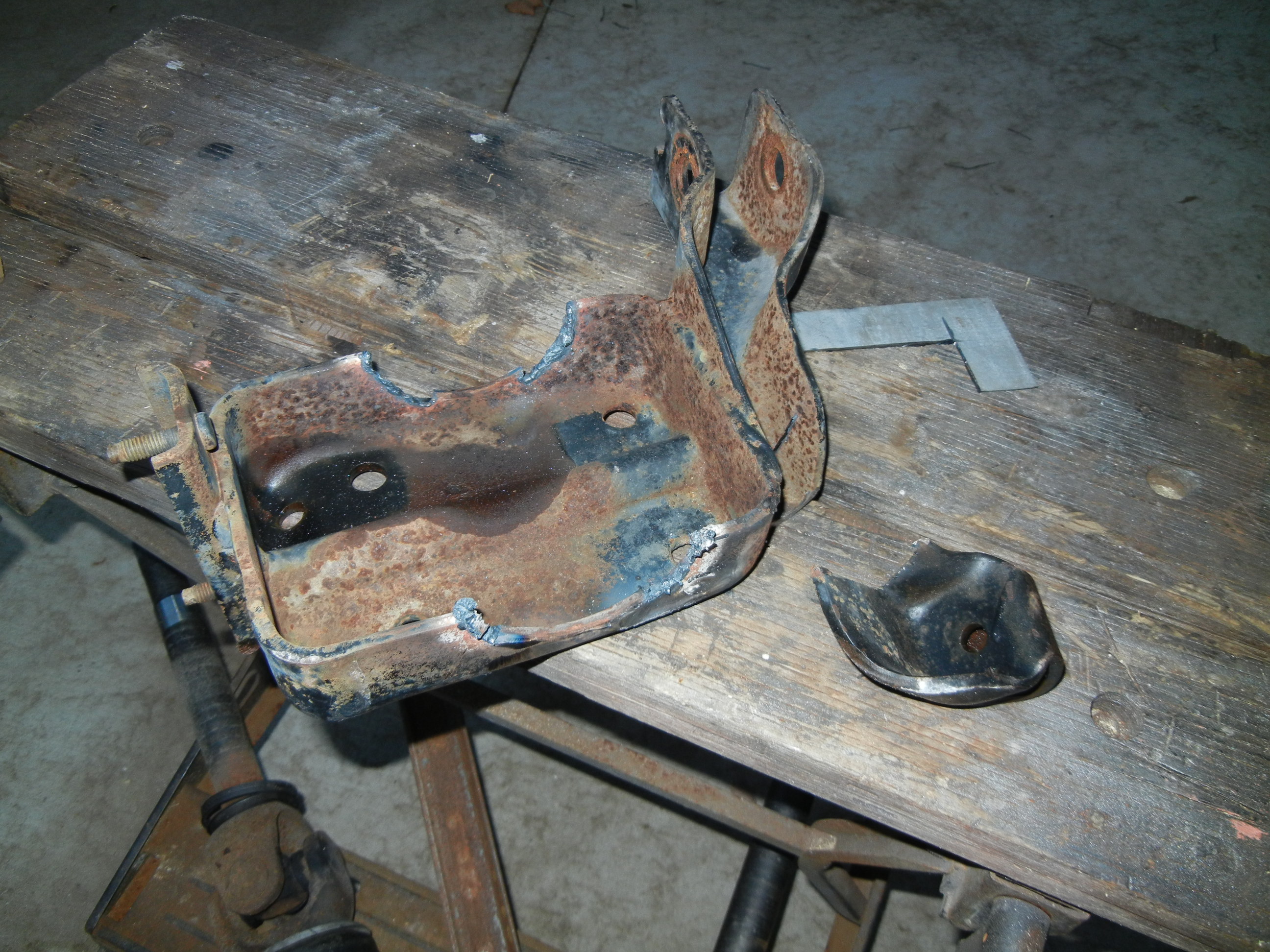
It was removed from a late (almost '05 coil sprung) 2004 F-250 that never worked a day in its life because it couldn't (5.4 gasser)! Judging by the condition of the front cover, this truck has done a lot of curb-hopping on the skinny street tires!
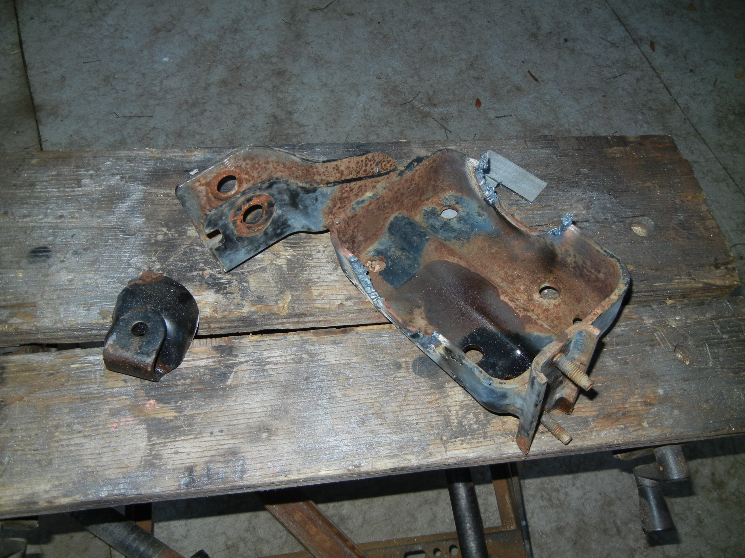
So then the usual, drain oil, remove components, torch off useless factory brackets, cut off inner C's, remove driver's side stubby tube. Wait, what?! Yep, I got this axle dirt cheap, so let's see if we can attempt to remove the short stubby tube and install a longer tube so that it can be used in another vehicle. If we damage or destroy it, oh well- there's a million more out there to grab!
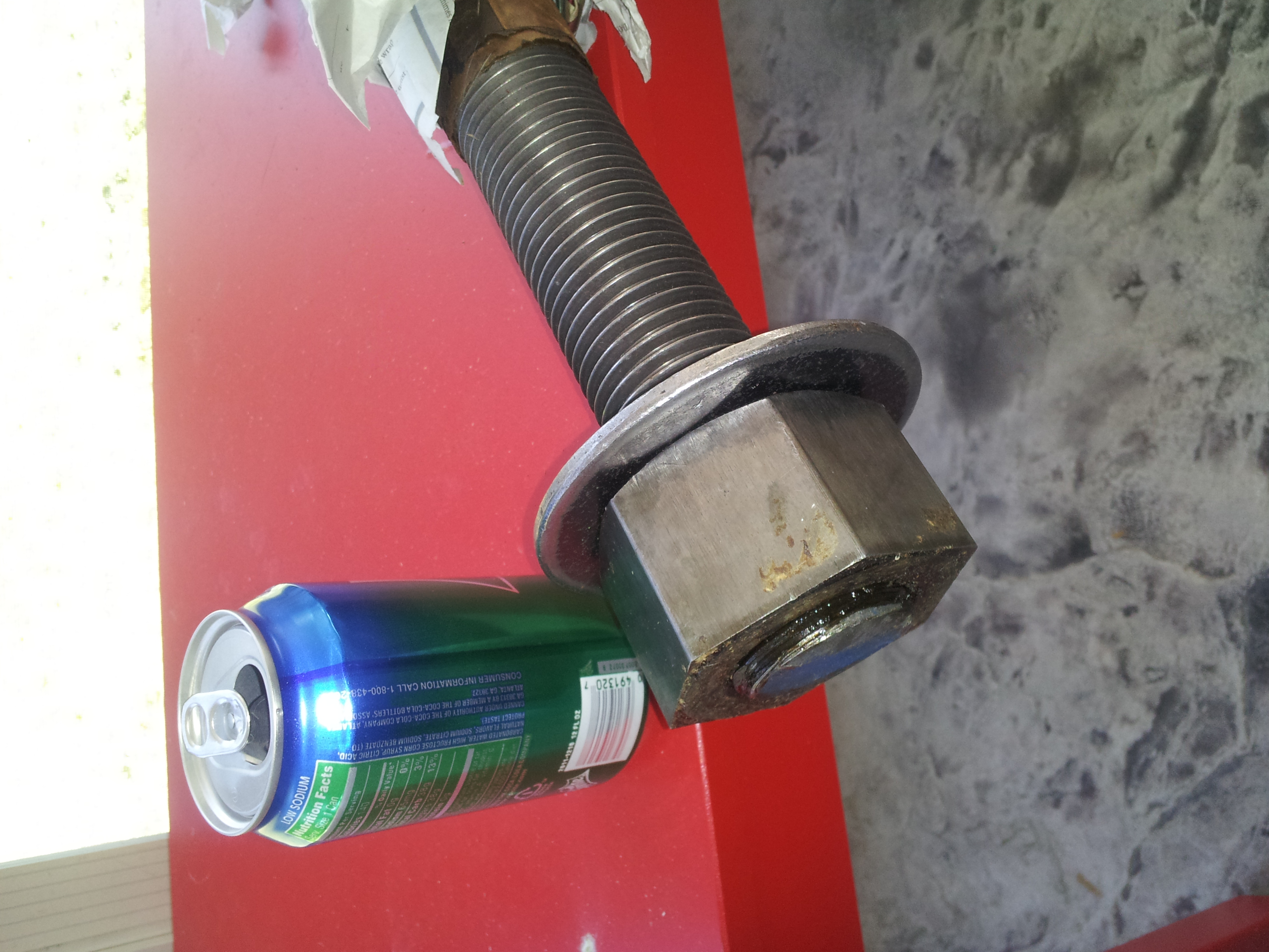
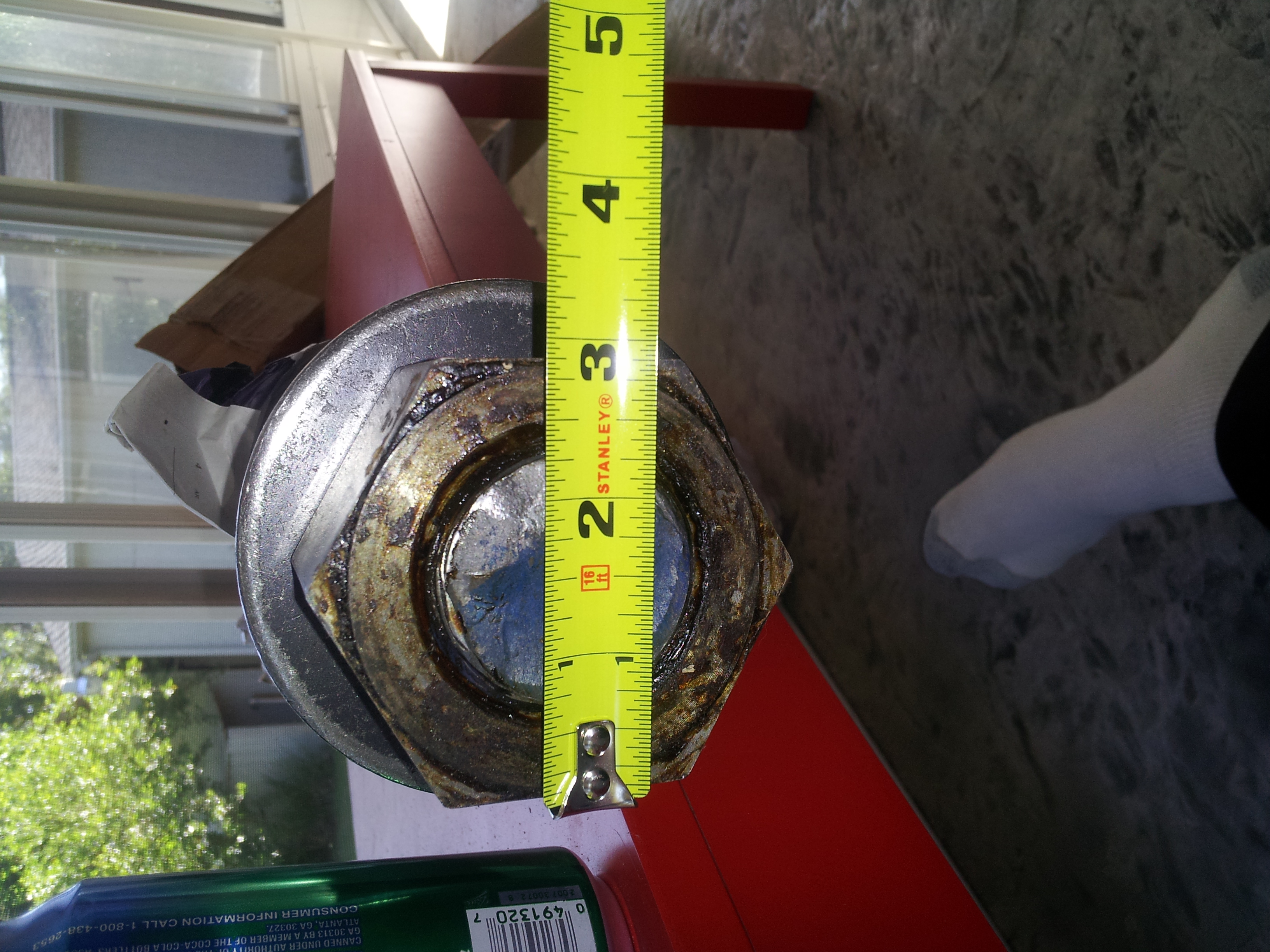
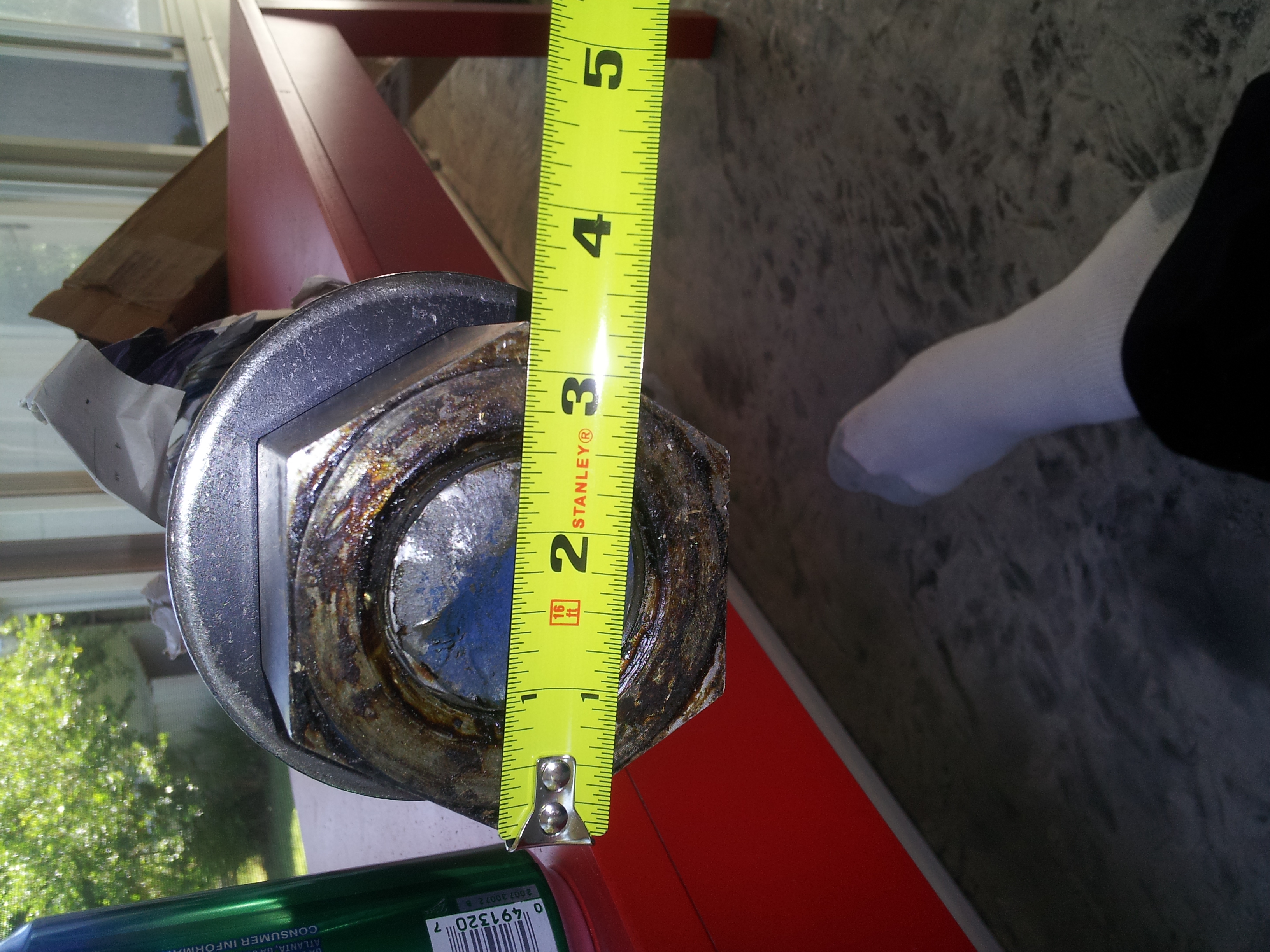
Here is the problem: a short tube that many people leave in place and actually cut back the housing to expose more of the tube in order to weld suspension brackets to. I guess that works for lightweight gas powered trail rigs. Searching online shows several methods from DIY'ers ranging from slicing out the tube from the inside, beating on the C relentlessly to eventually force it out, pressing it out using a mini-ram from inside the housing, using a horizontal bottle jack press or even a forklift and chains but the method that most appealed to us was by using a threaded rod and nut to apply a controlled amount of force on the tube and outside of the housing. The other methods may have worked great on Dana 30's, 44's and even 10-bolts, but we were playing with D60 sized stuff. I searched around and landed a deal on eBay for a 1-7/8" threaded rod 36" long, washer and heavy hex nut to do the job. This thing is big!
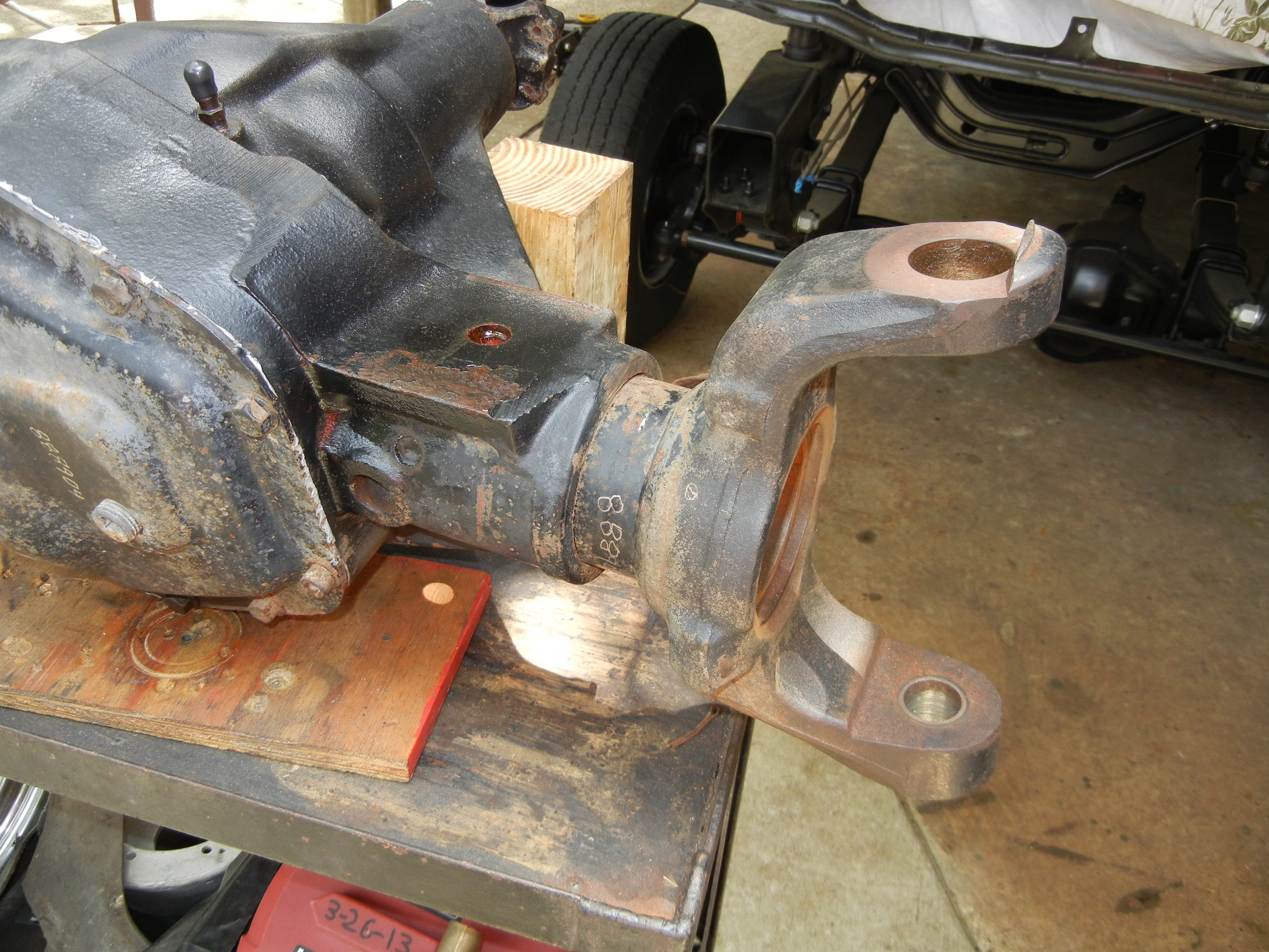
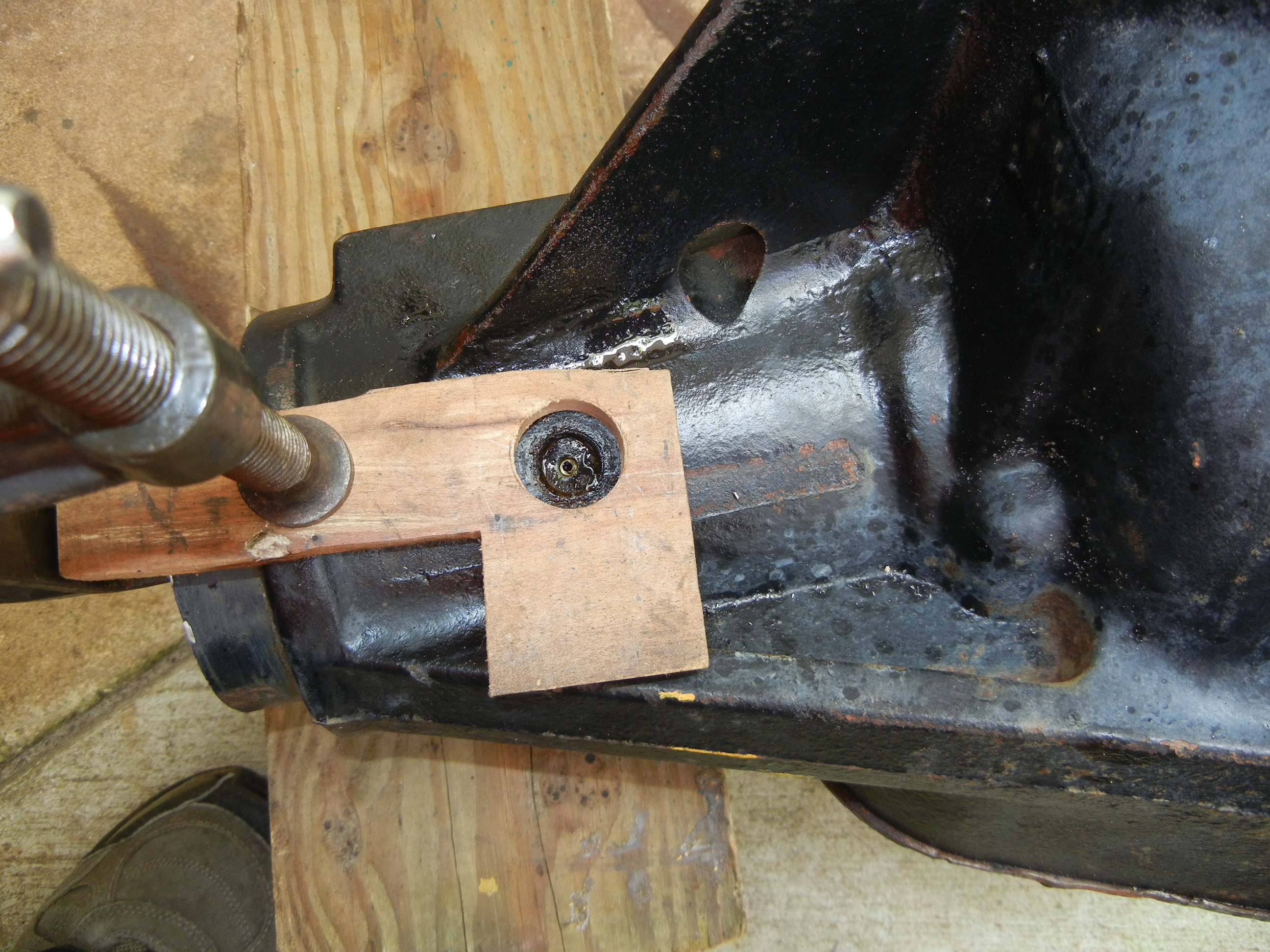
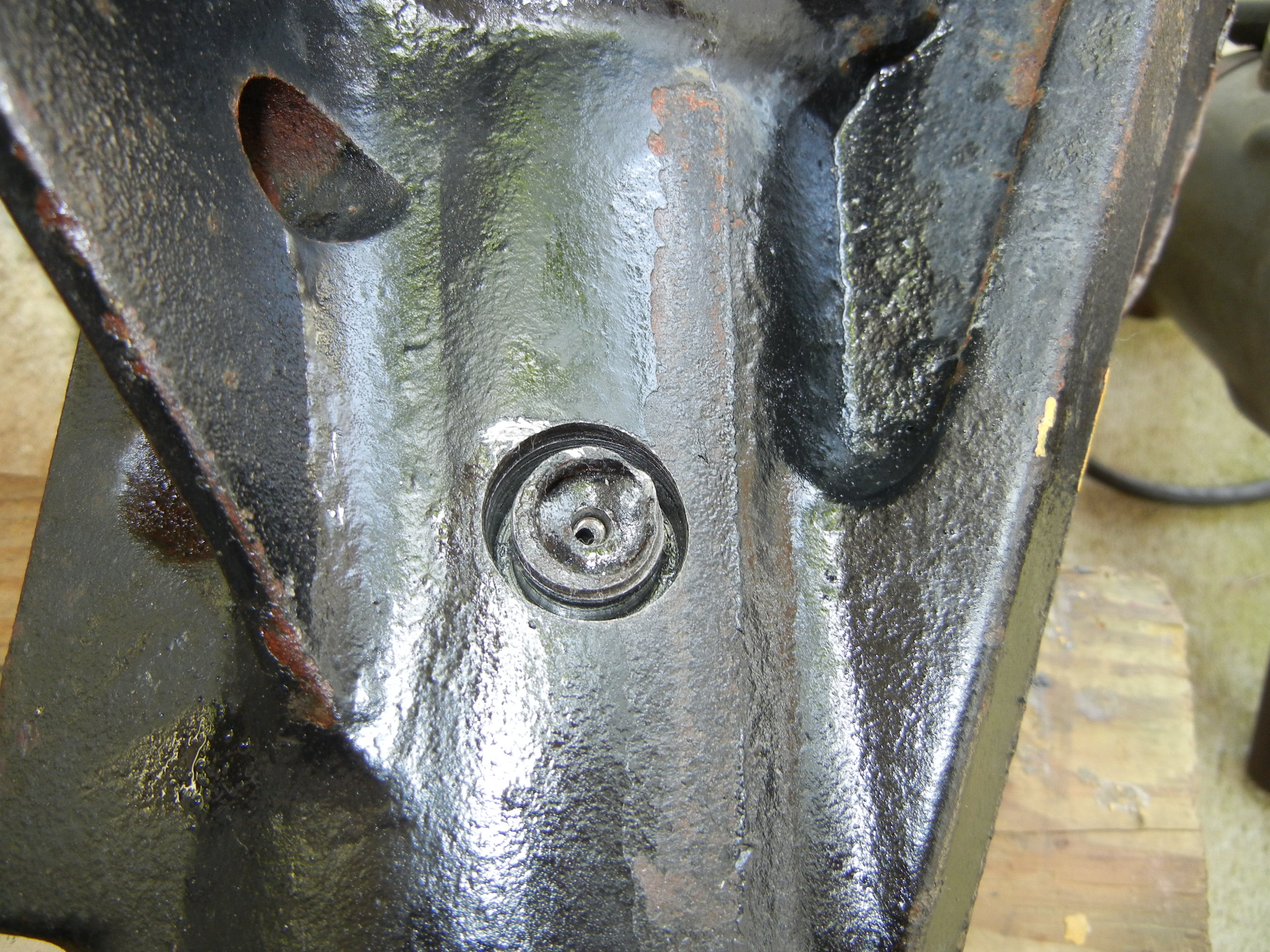
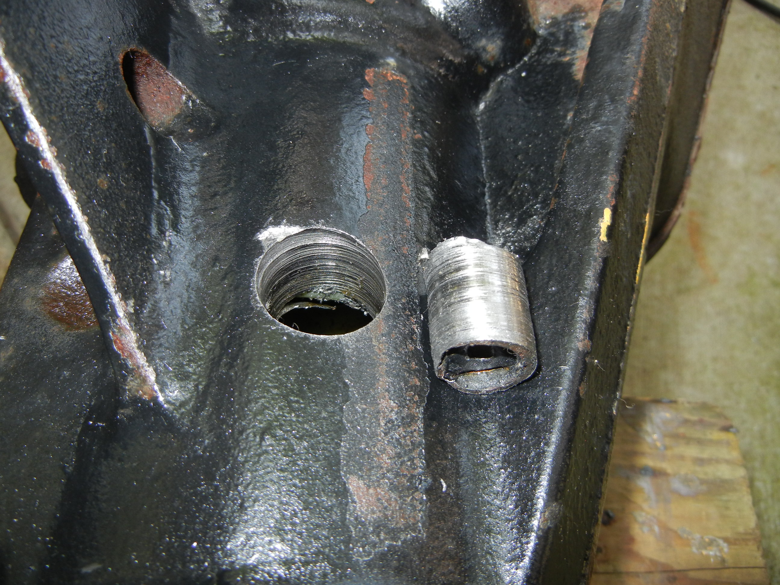
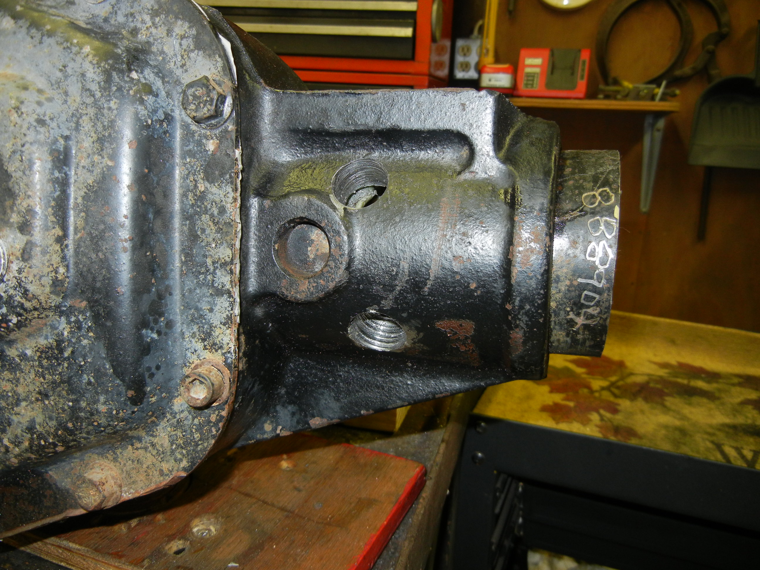
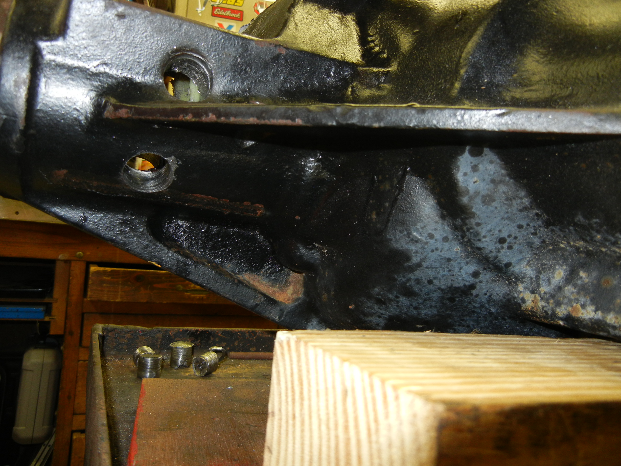
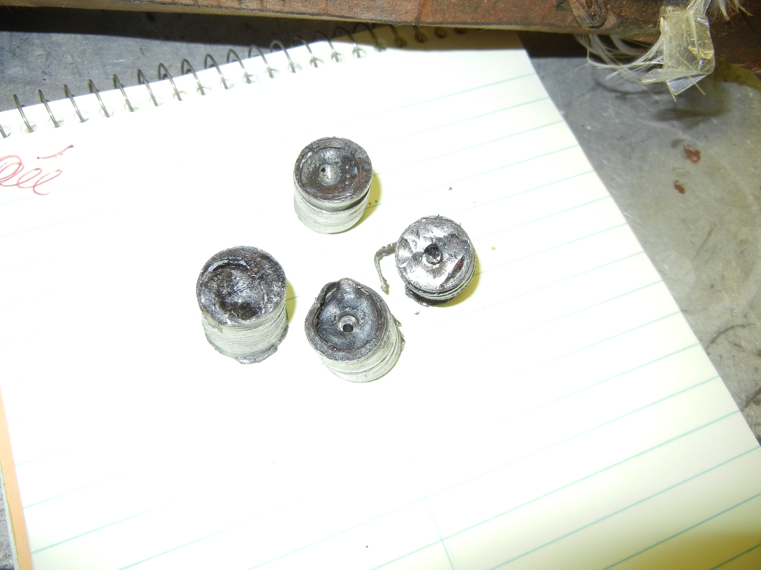
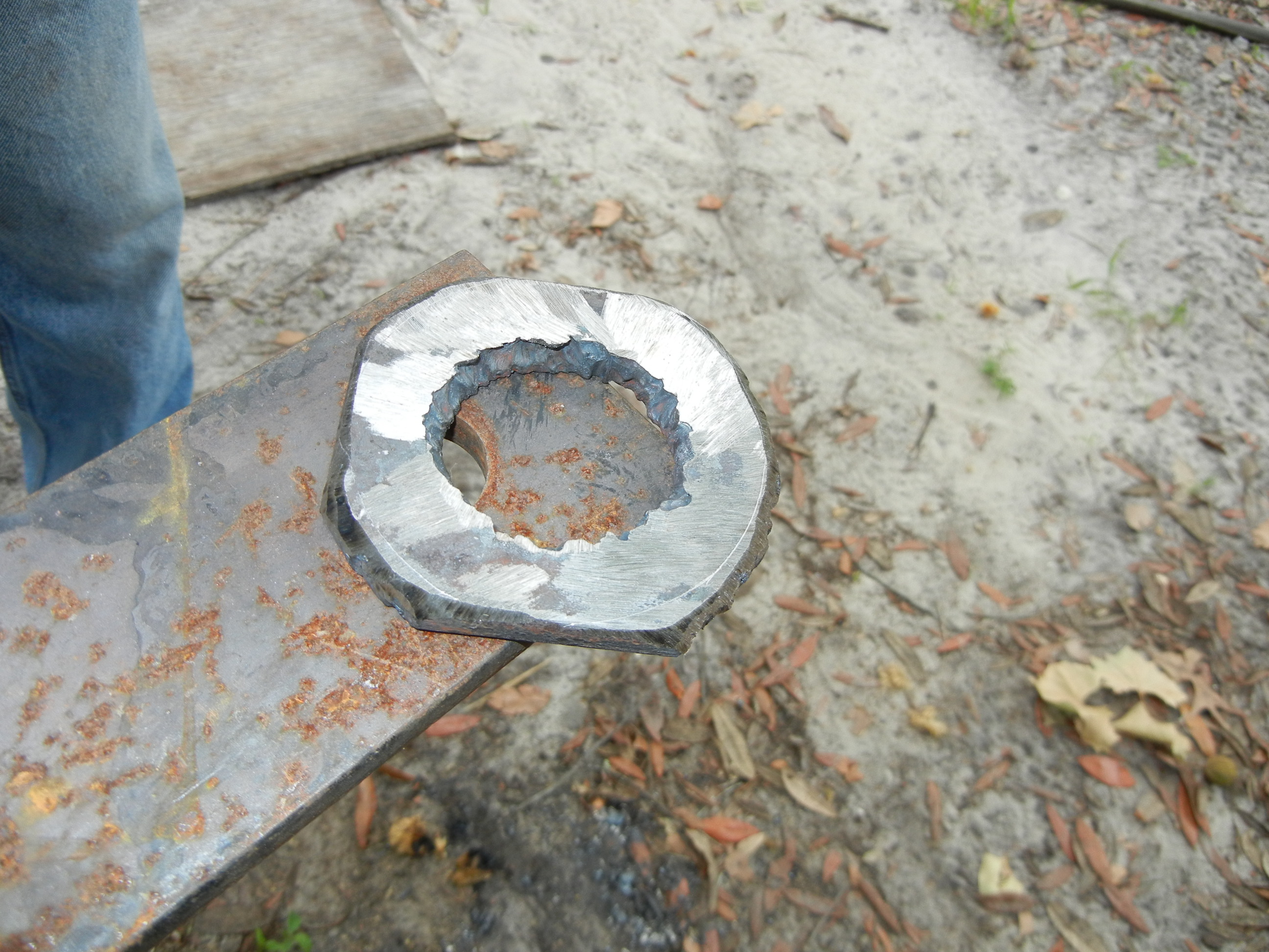
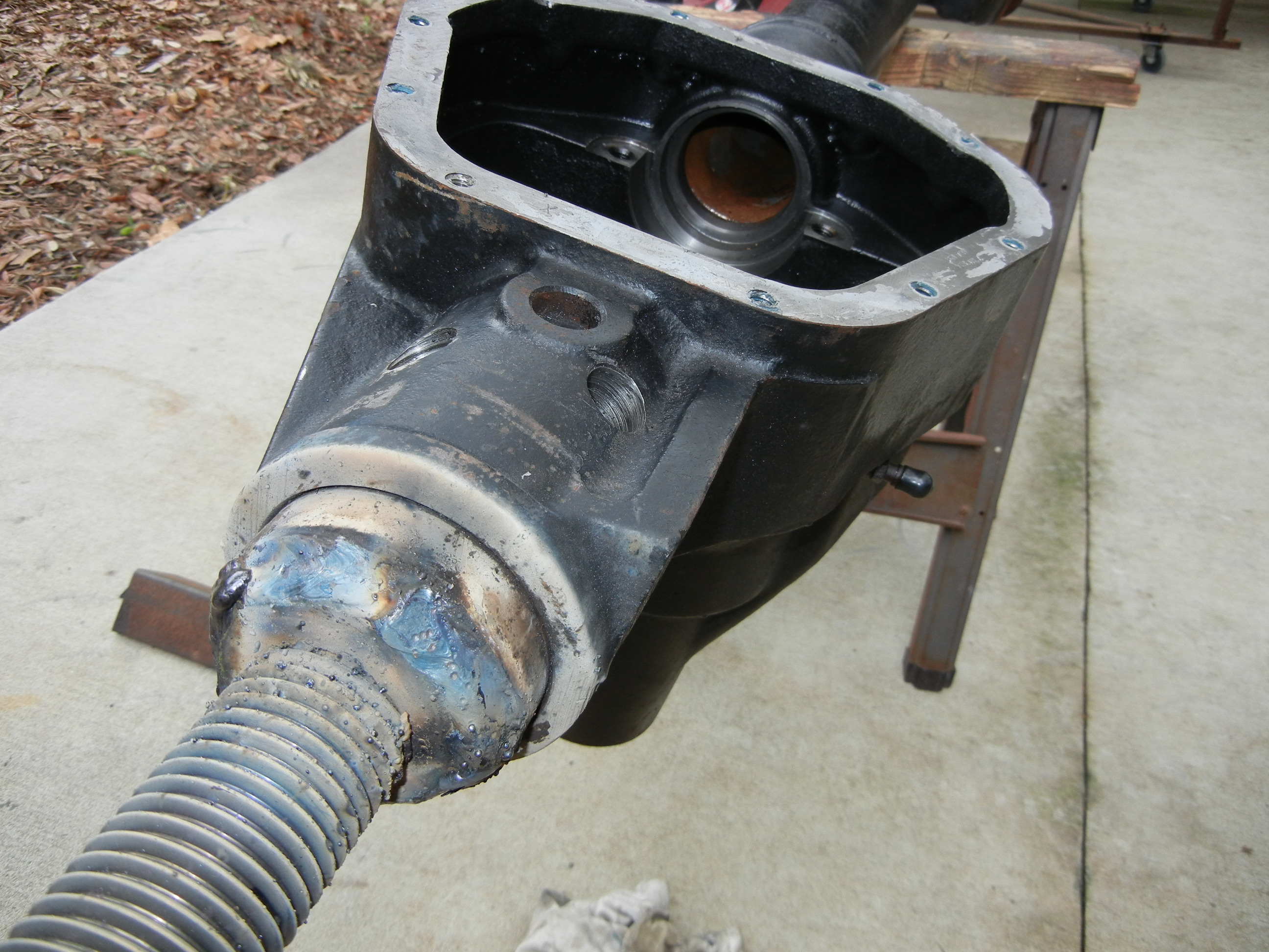
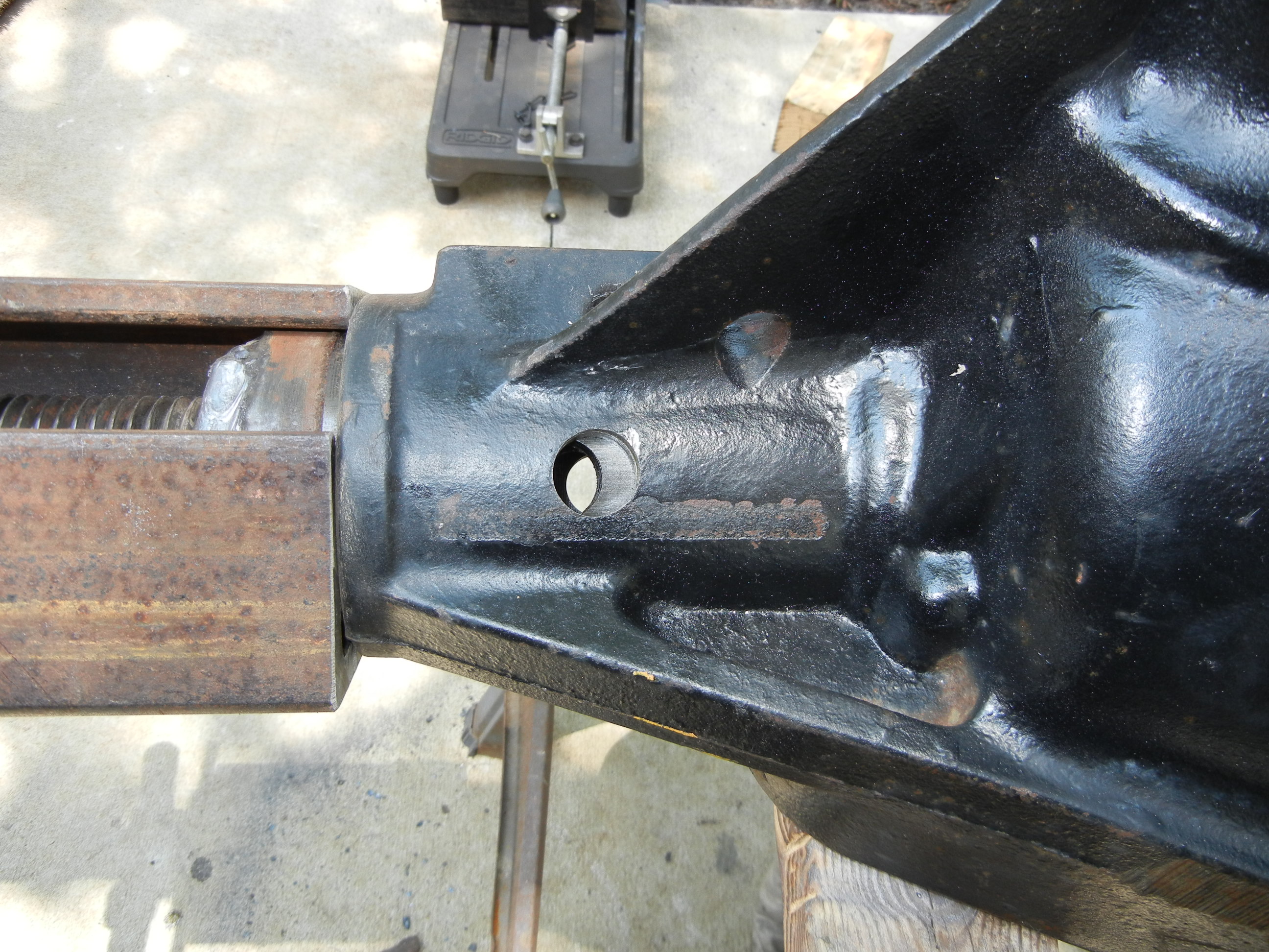
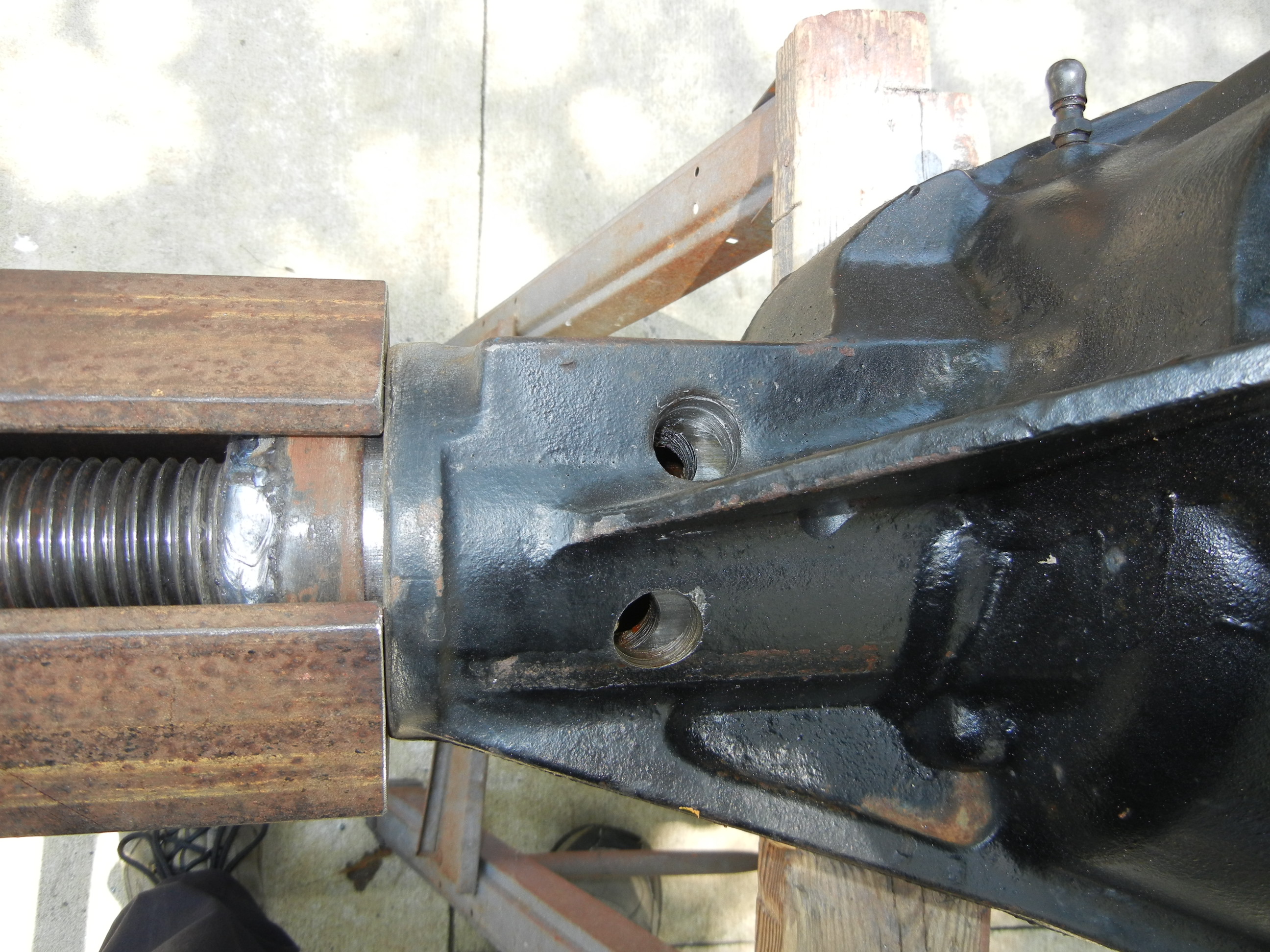
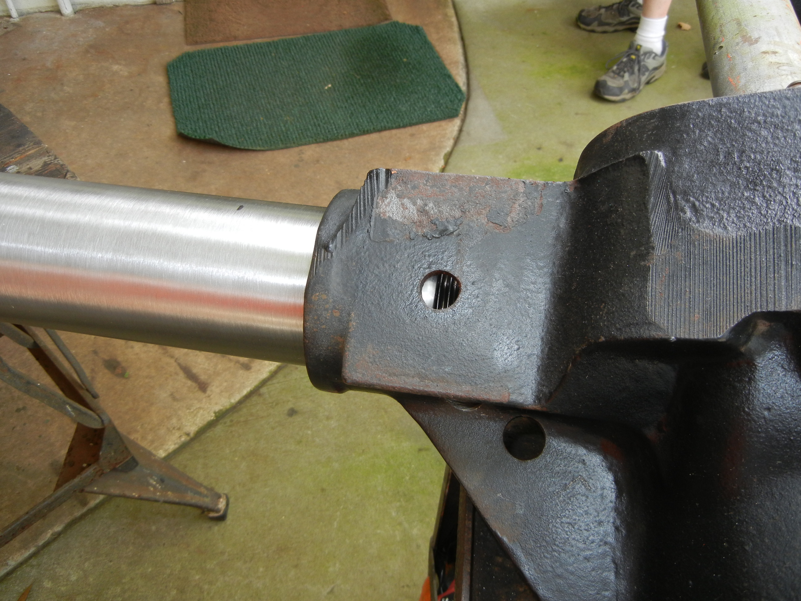
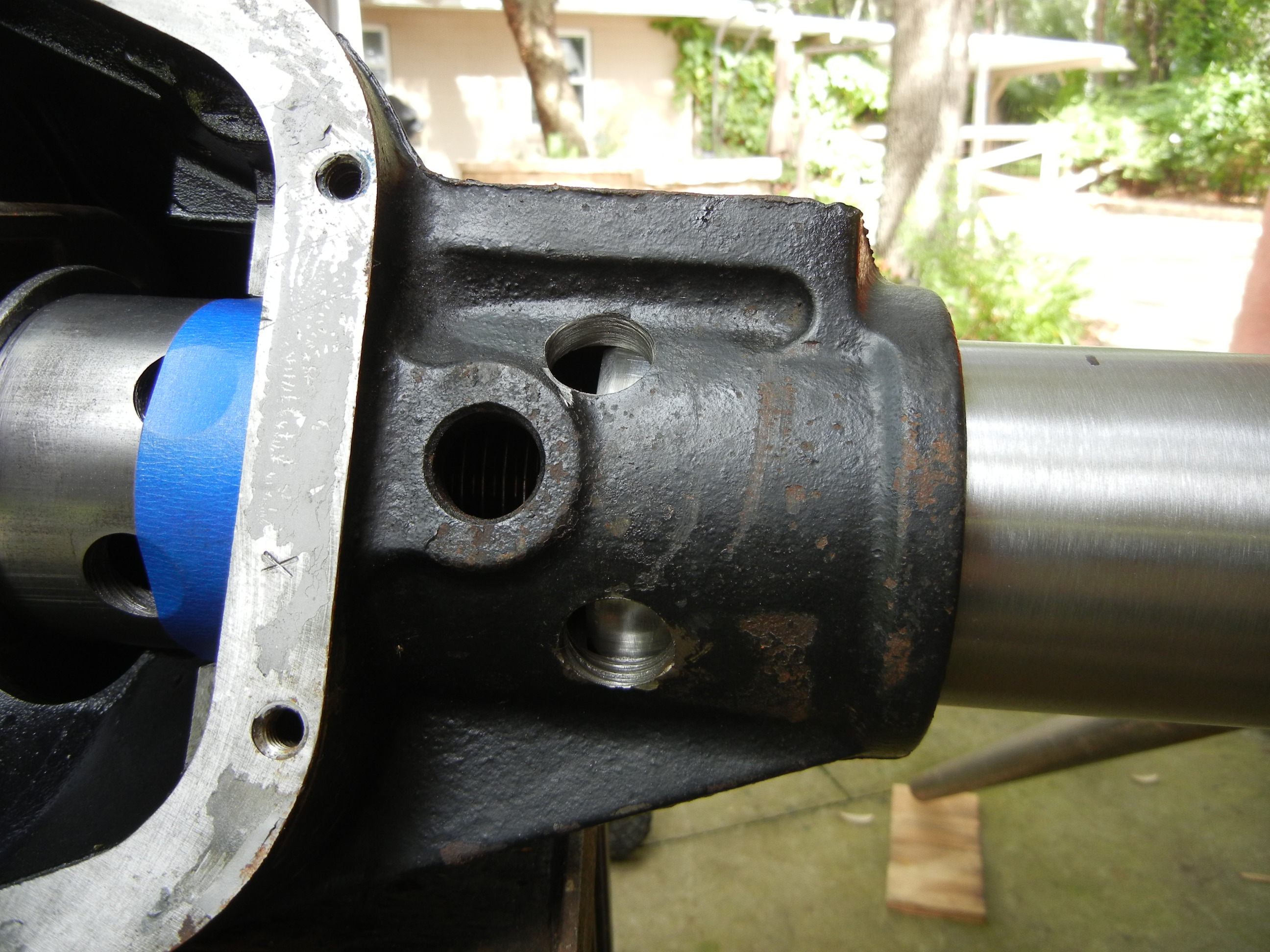
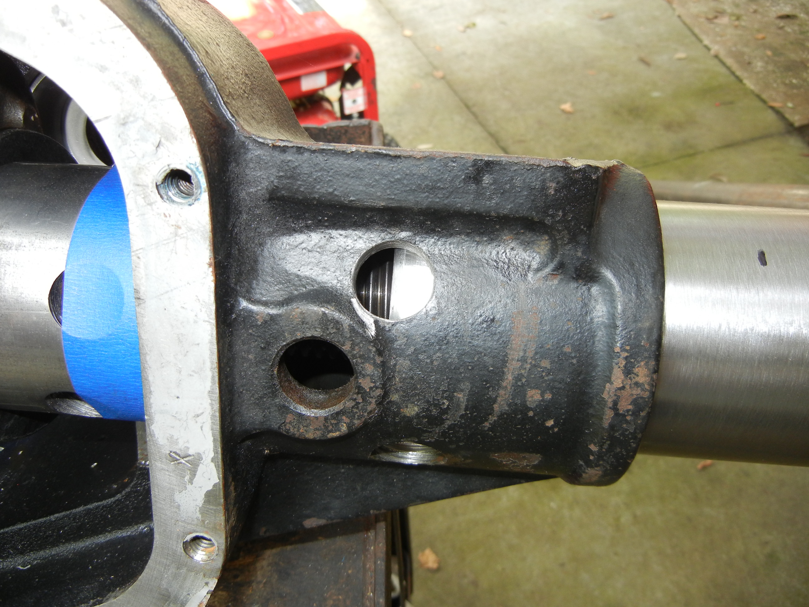
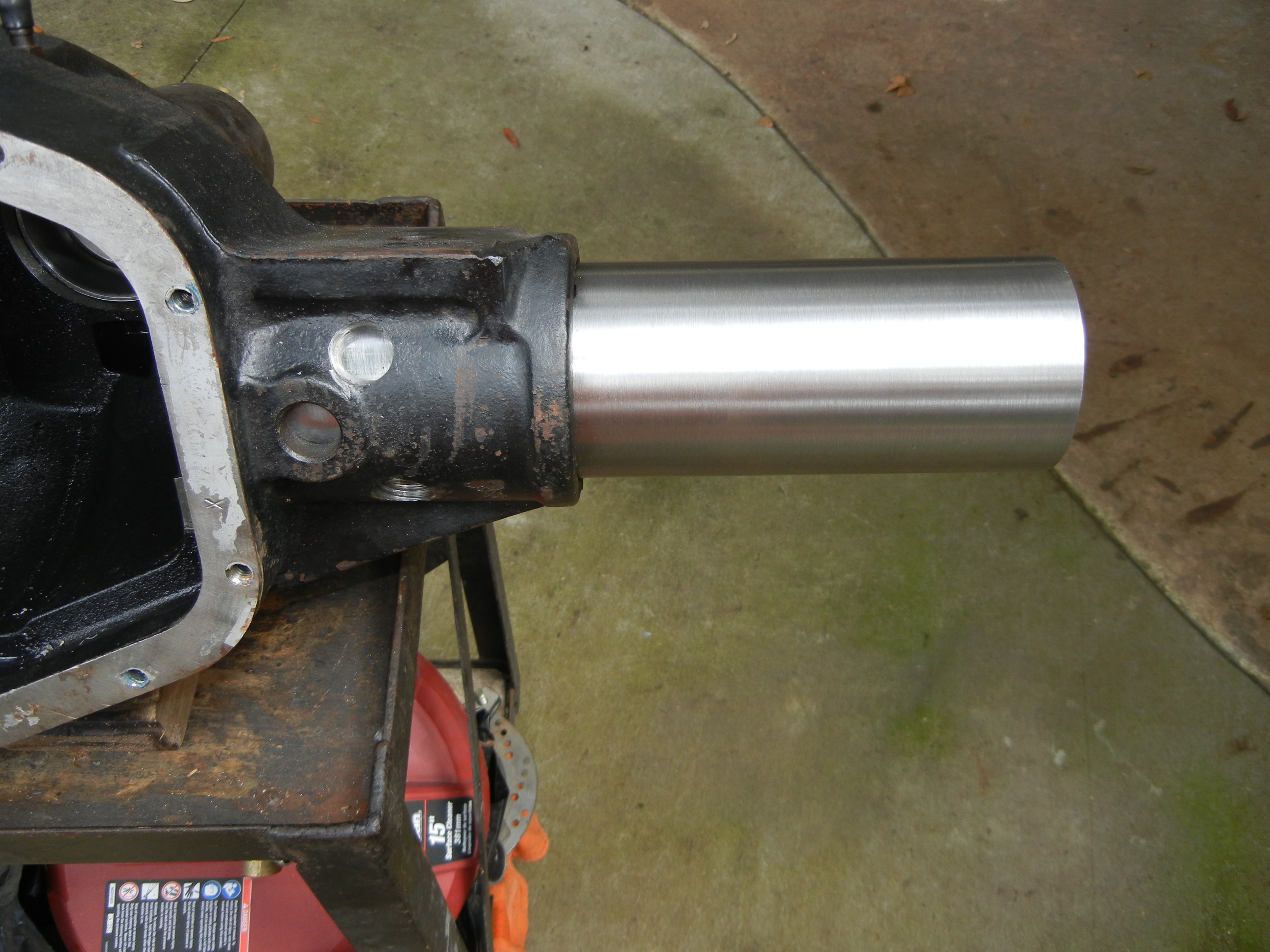
I also ordered up a new DOM tube that measures 3.5"OD x 3/8" wall thickness that is right at 12" long. Before spending (wasting) any more money, it was time to see if this was all just a waste of time or if it would actually 'amount' to something. First the C was cut off exposing the end of the tube. It is important to note the tube thickness is actually 0.35" for the F250/350 and F350 DRW models and is 0.4375" for the F450/550 models (more on this later and yes we have pics). Then came time to remove the plug welds. Some people burn them out with a torch or gouging rod, but I 'tried' to take a more civilized approach by drilling them out to the diameter of the original cast hole (1/2"). We realized the plug welds were very hard steel (probably Ni99 rod) and kept breaking/chipping our drill bits. After 10 or so sharpenings I thought about buying cobalt drill bits but chickened out after I saw the price. My father (again to the rescue) realized we could use a standard 7/8" hole saw and just bore through both the cast and the tube. A block of wood with a hole was clamped down to keep it from walking around. Sure enough, complete success! Amazingly all of this was done with the cover on, carrier in place and some oil still inside!
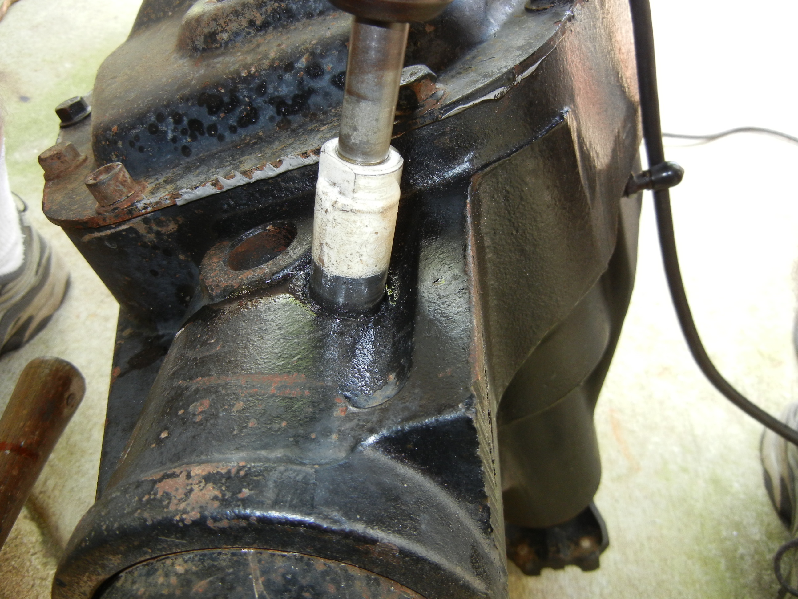
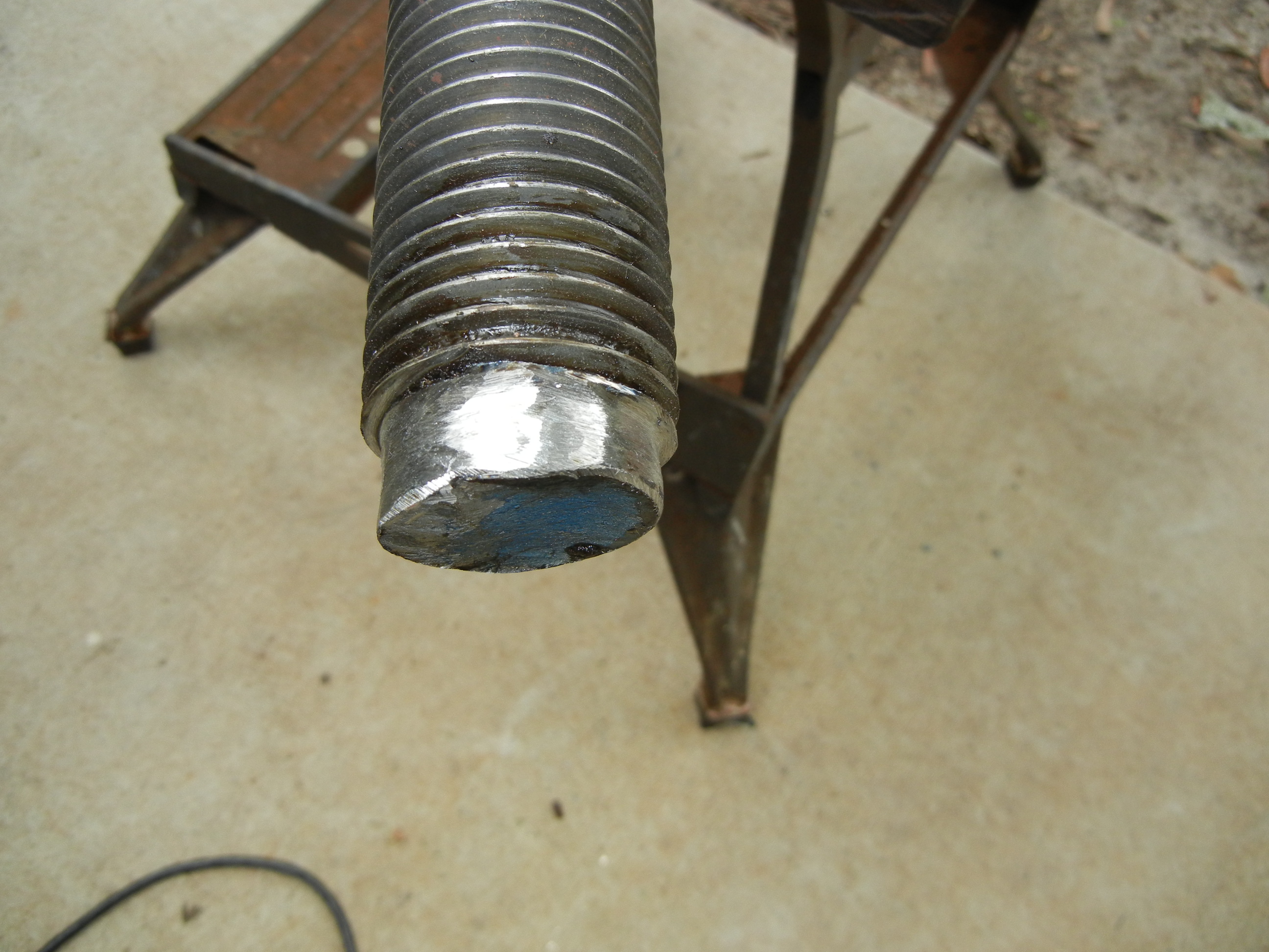
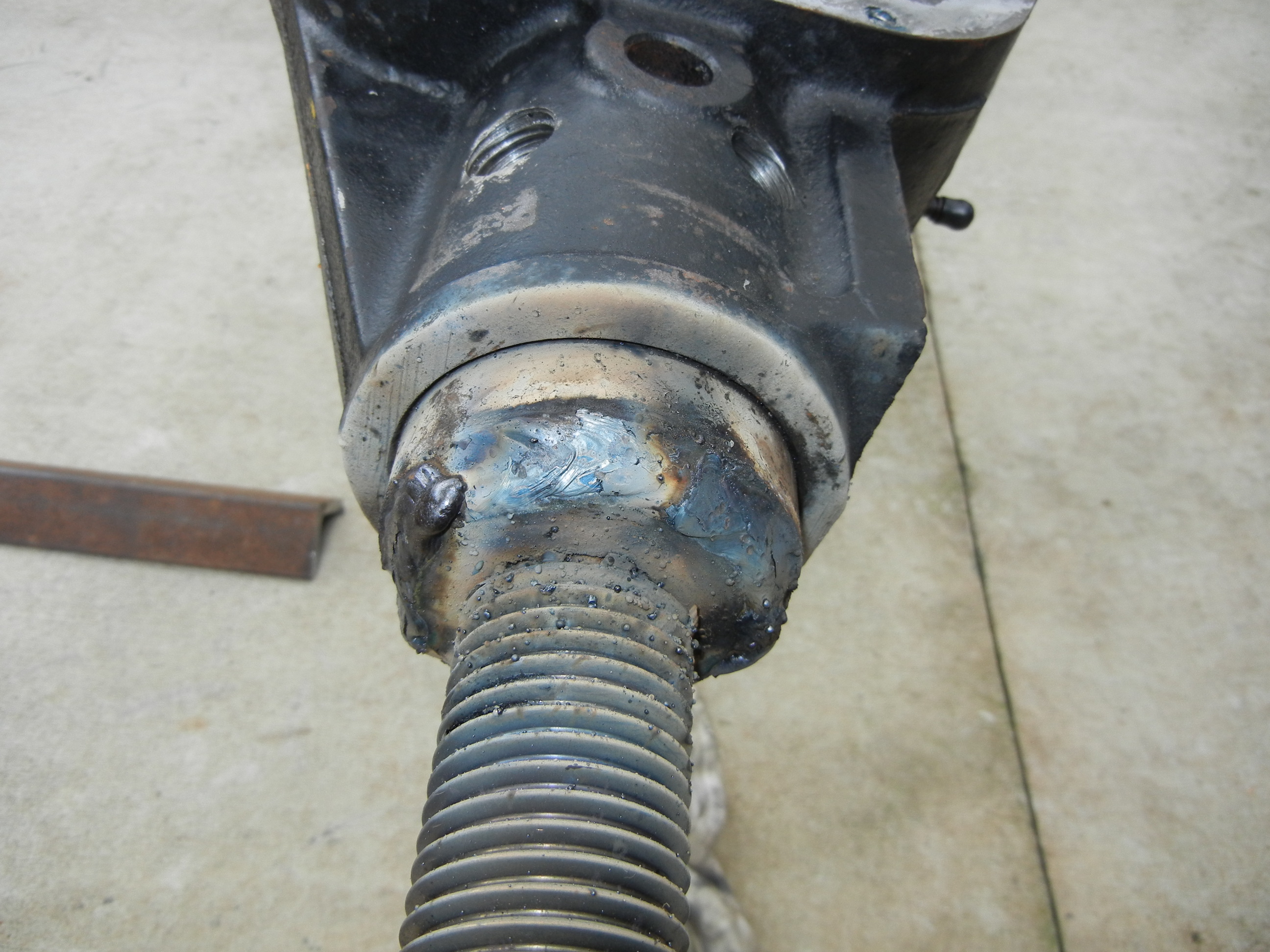
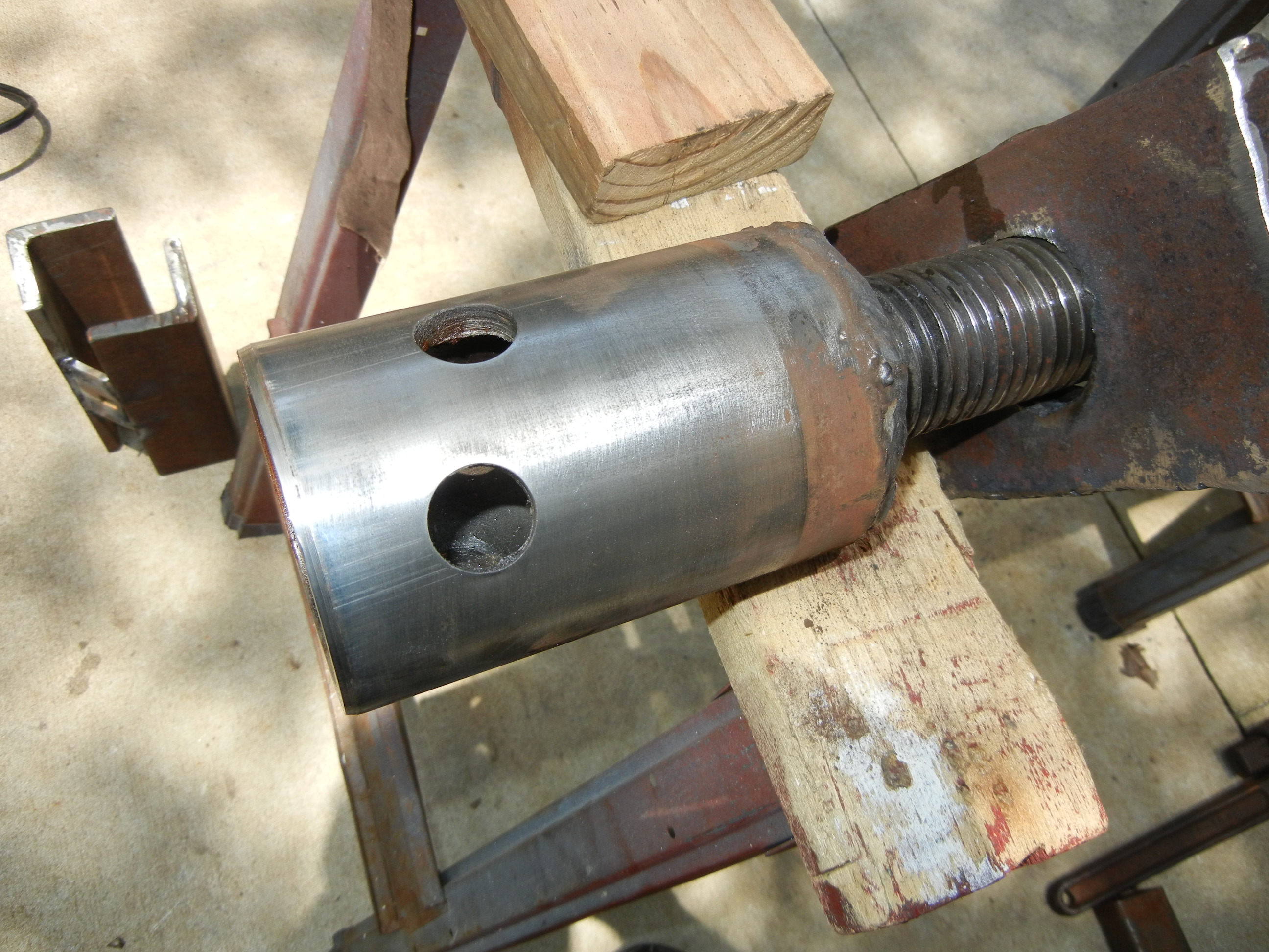
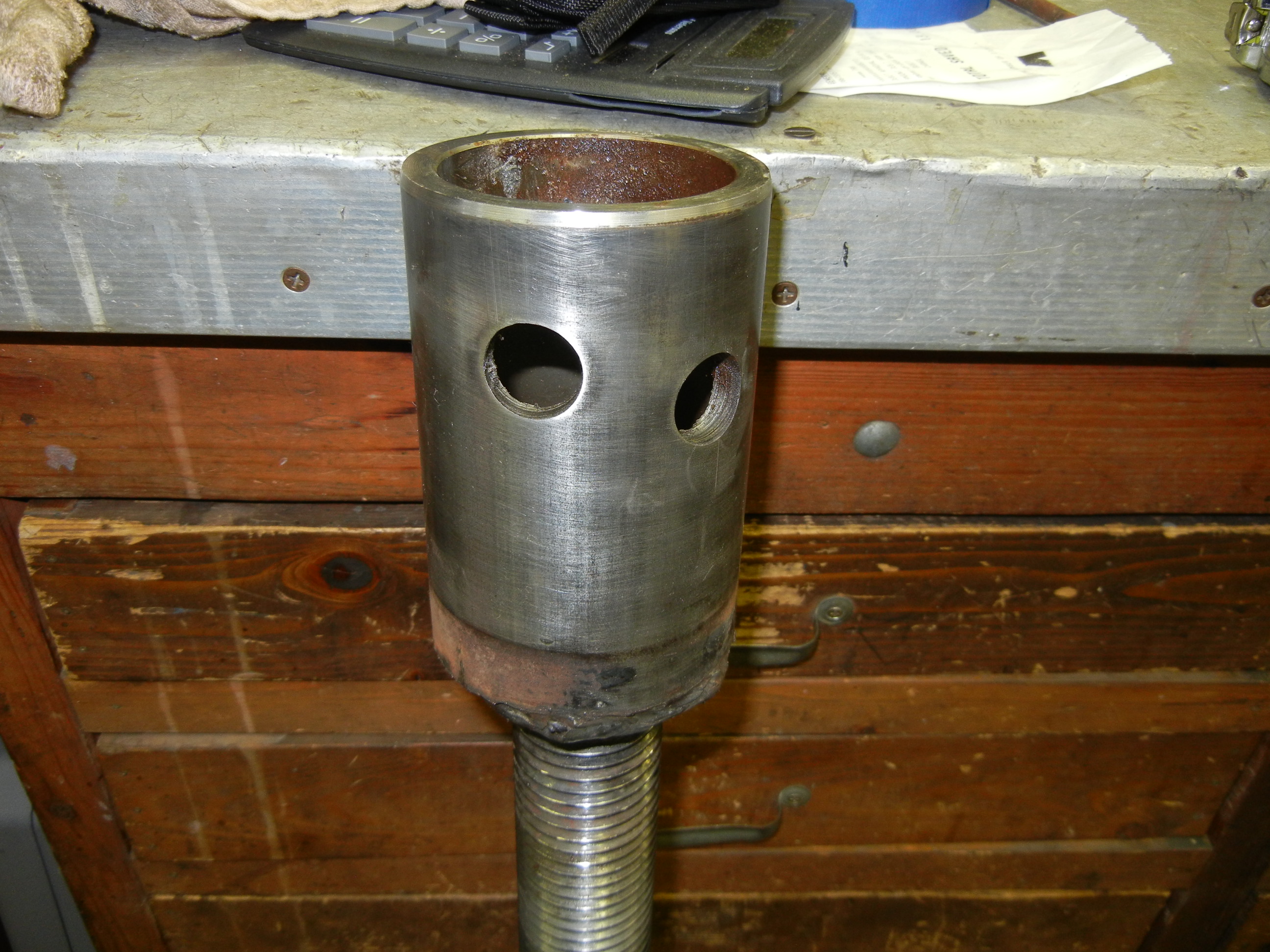
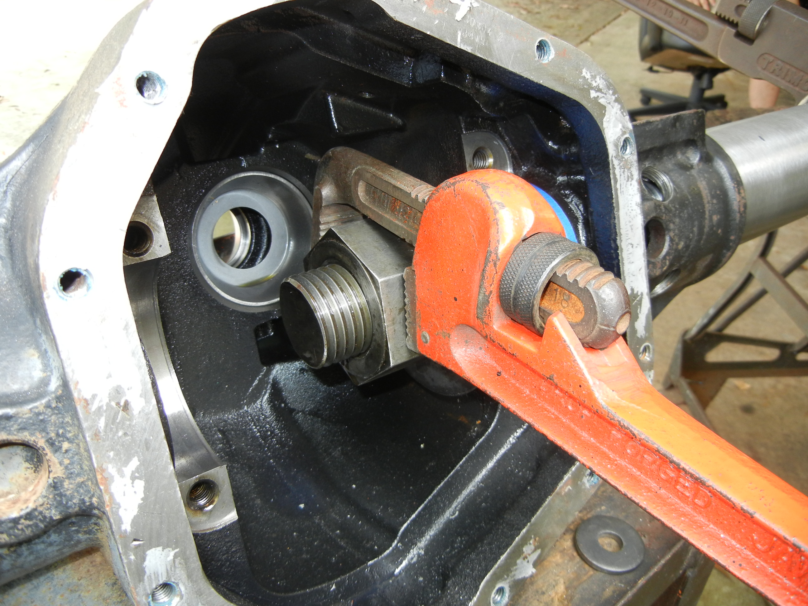
With the plug-slugs now out, it was time to fit the threaded rod to the end of the tube. The first few threads were ground down so a thick steel disc could be welded on. Then the unit was welded to the protruding tube after grinding a chamfer for more weld penetration. This part was welded with the stick welder @ 195A.
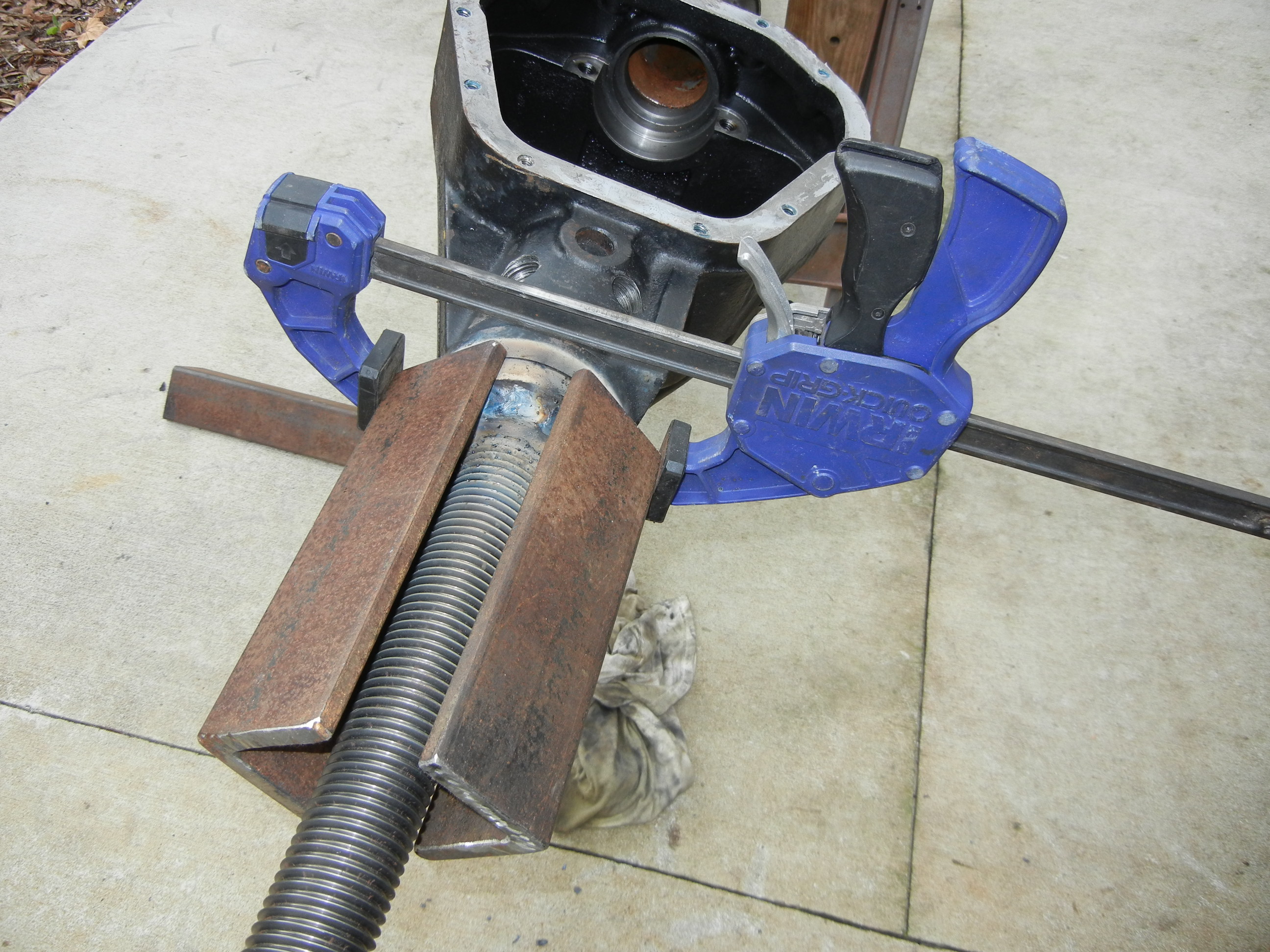
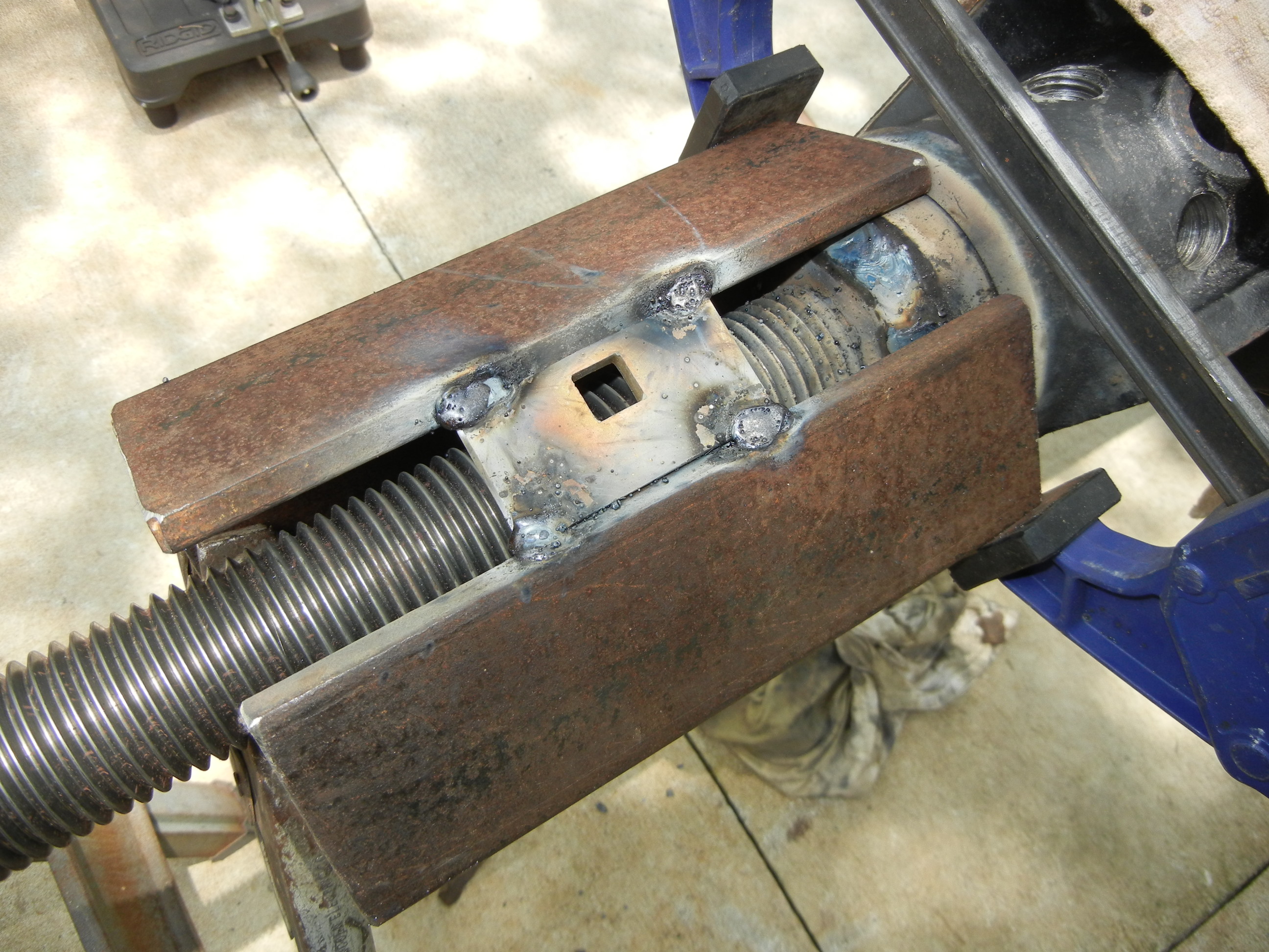
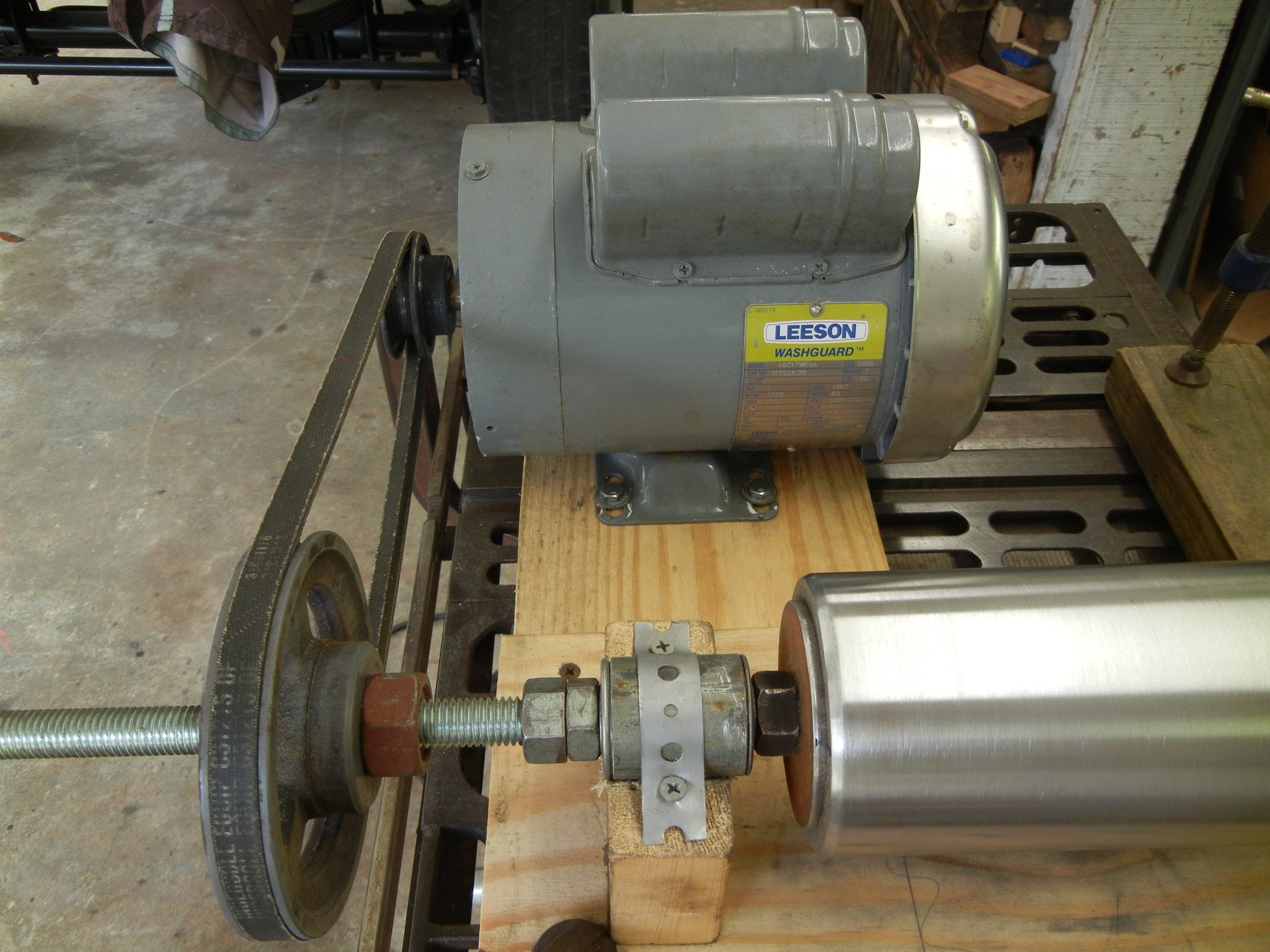
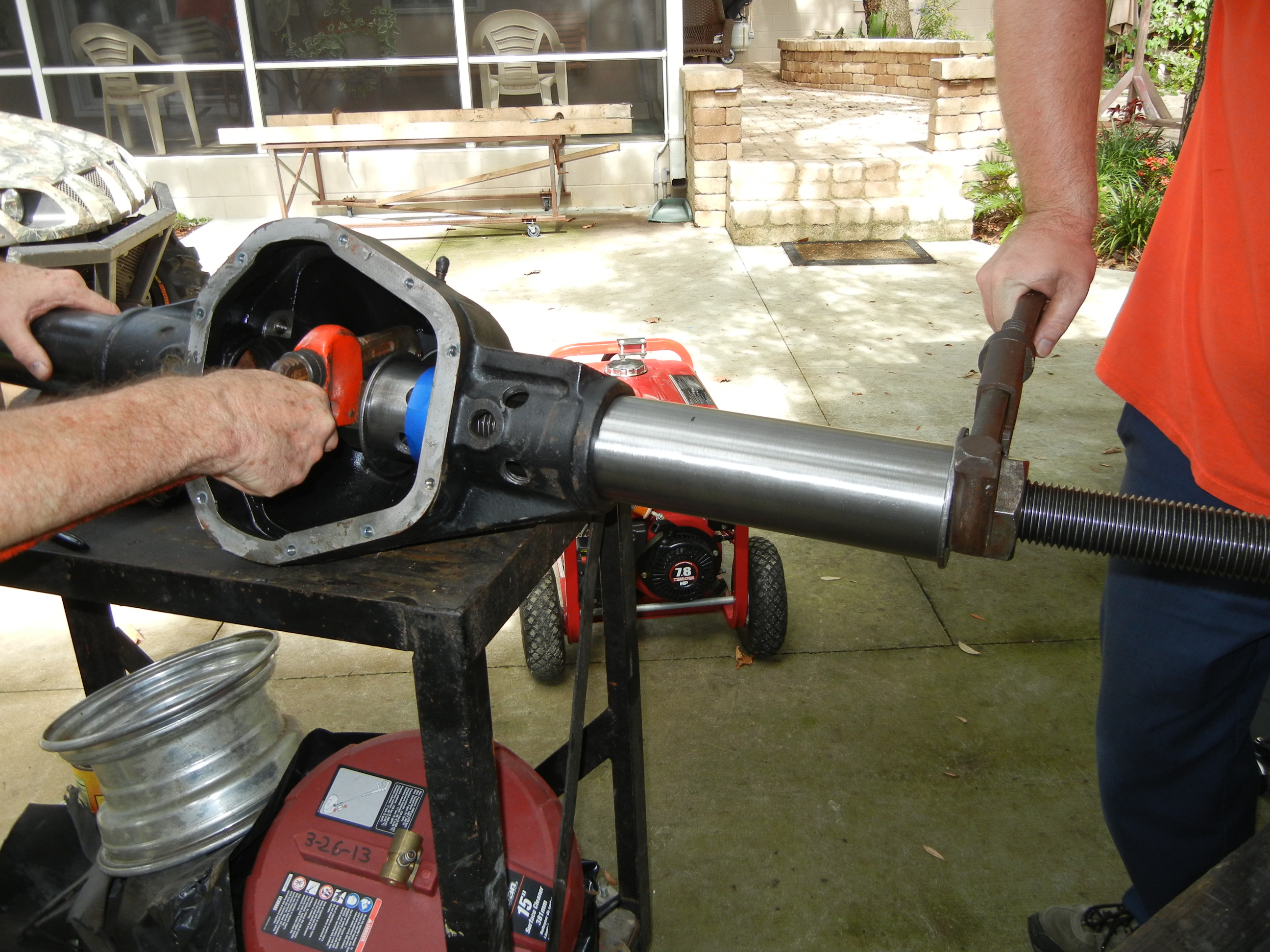
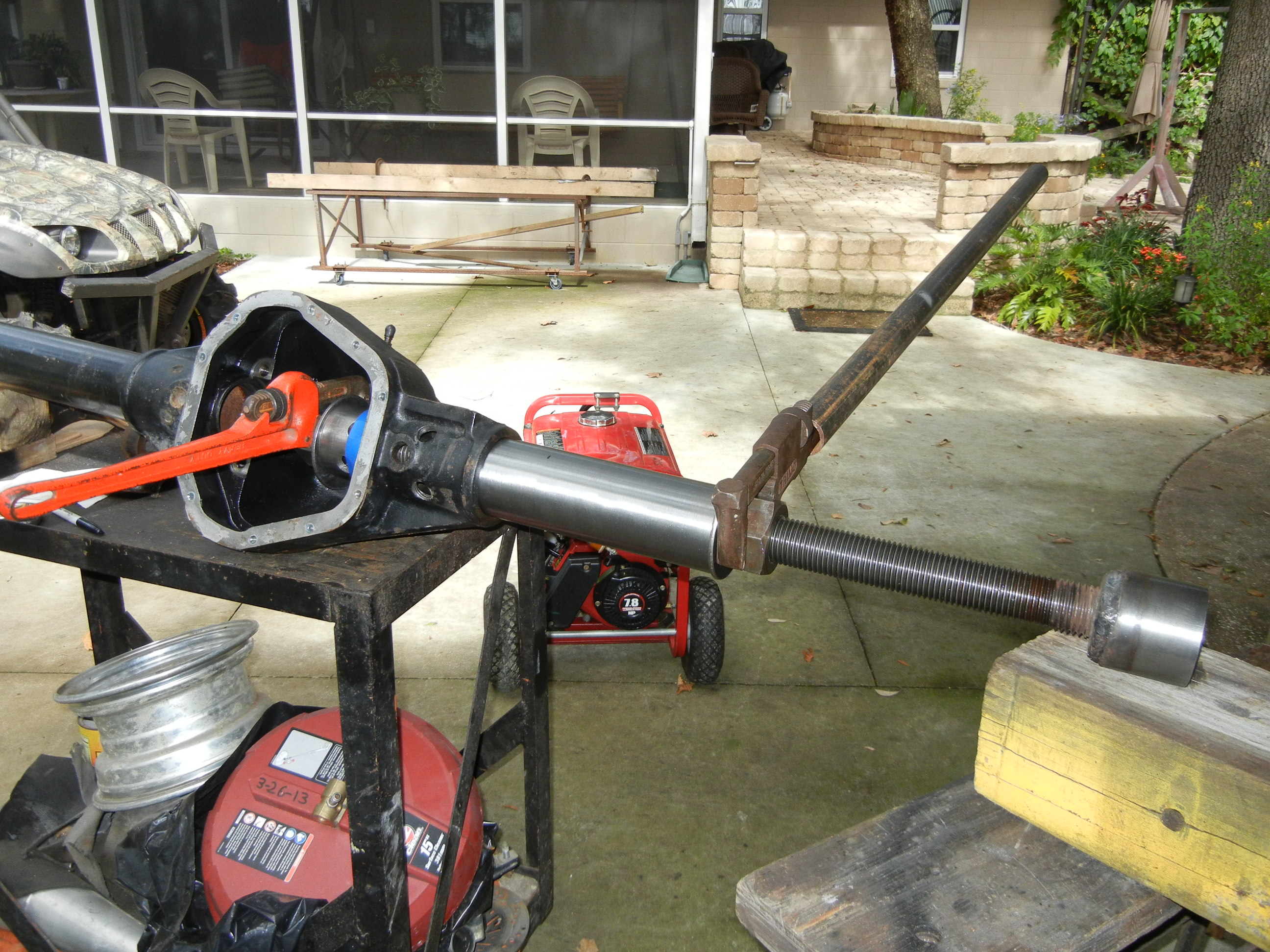
Last it was time to make the housing jig. We had some 1/2" angle iron laying around and used it to press against the circular end of the cast housing. A small plate was welded in to keep it all together instead of relying on the quick-clamp. It was now GO TIME!
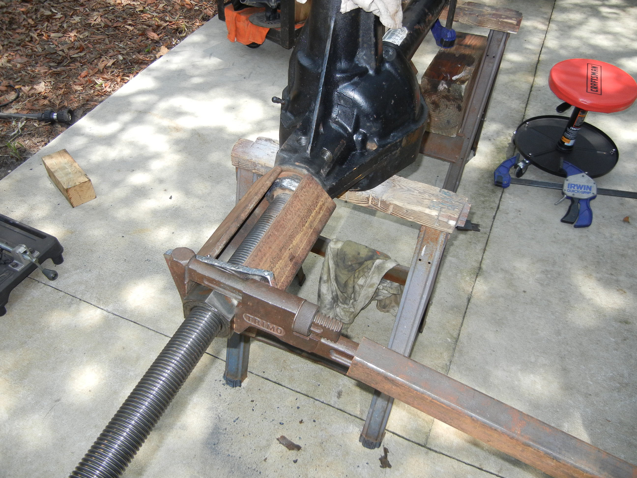
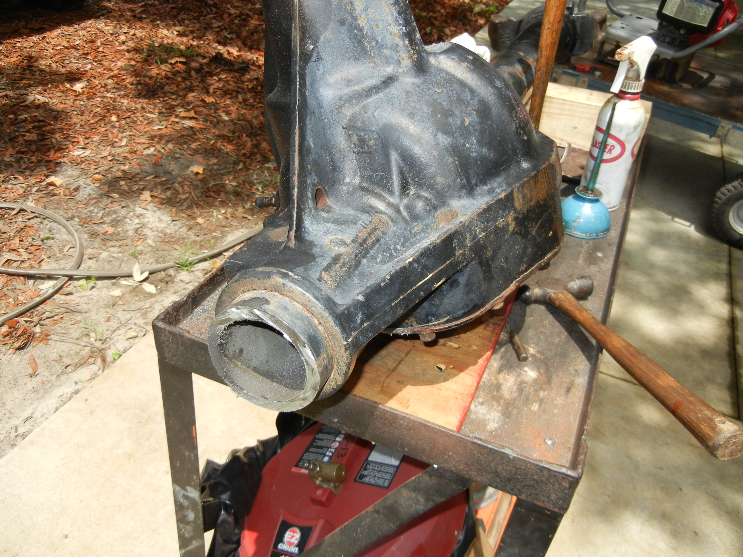
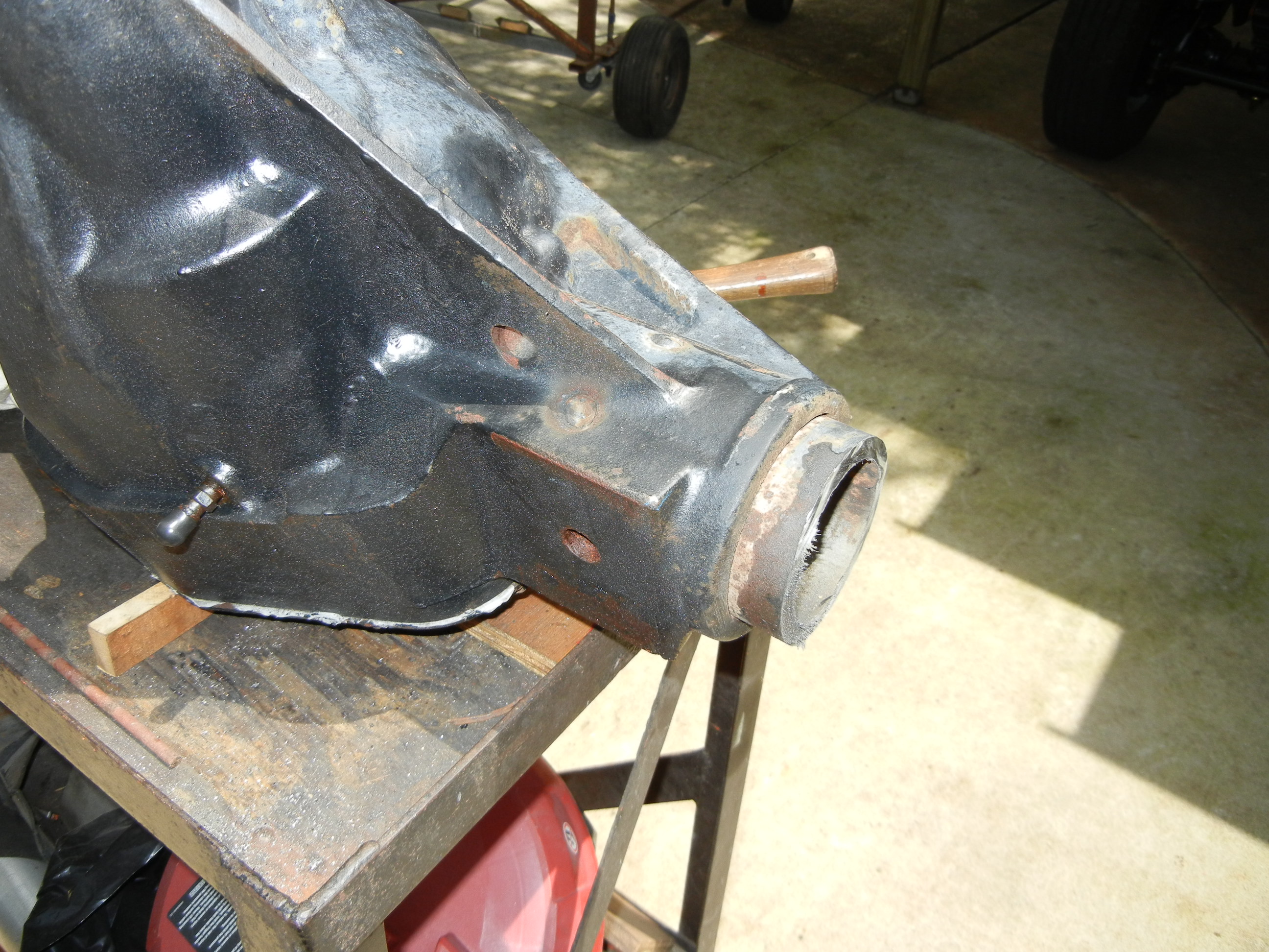
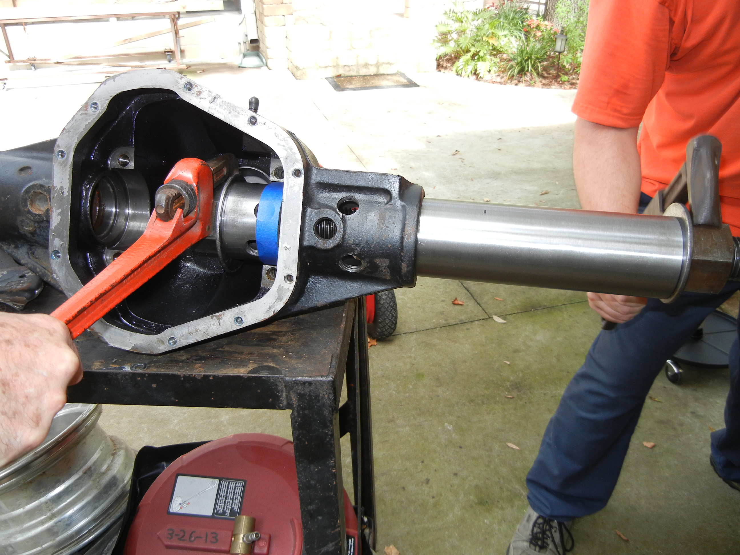
With cheater bars on both the pipe wrench and the other C on the passenger side (we're glad we didn't cut it off yet!), we tightened the nut as much as we could and eventually the tube started sliding out! It was a very tight fit and the wrenching did not get easy until the tube was 3/4 or more out of the housing. As you can see no heat was used!
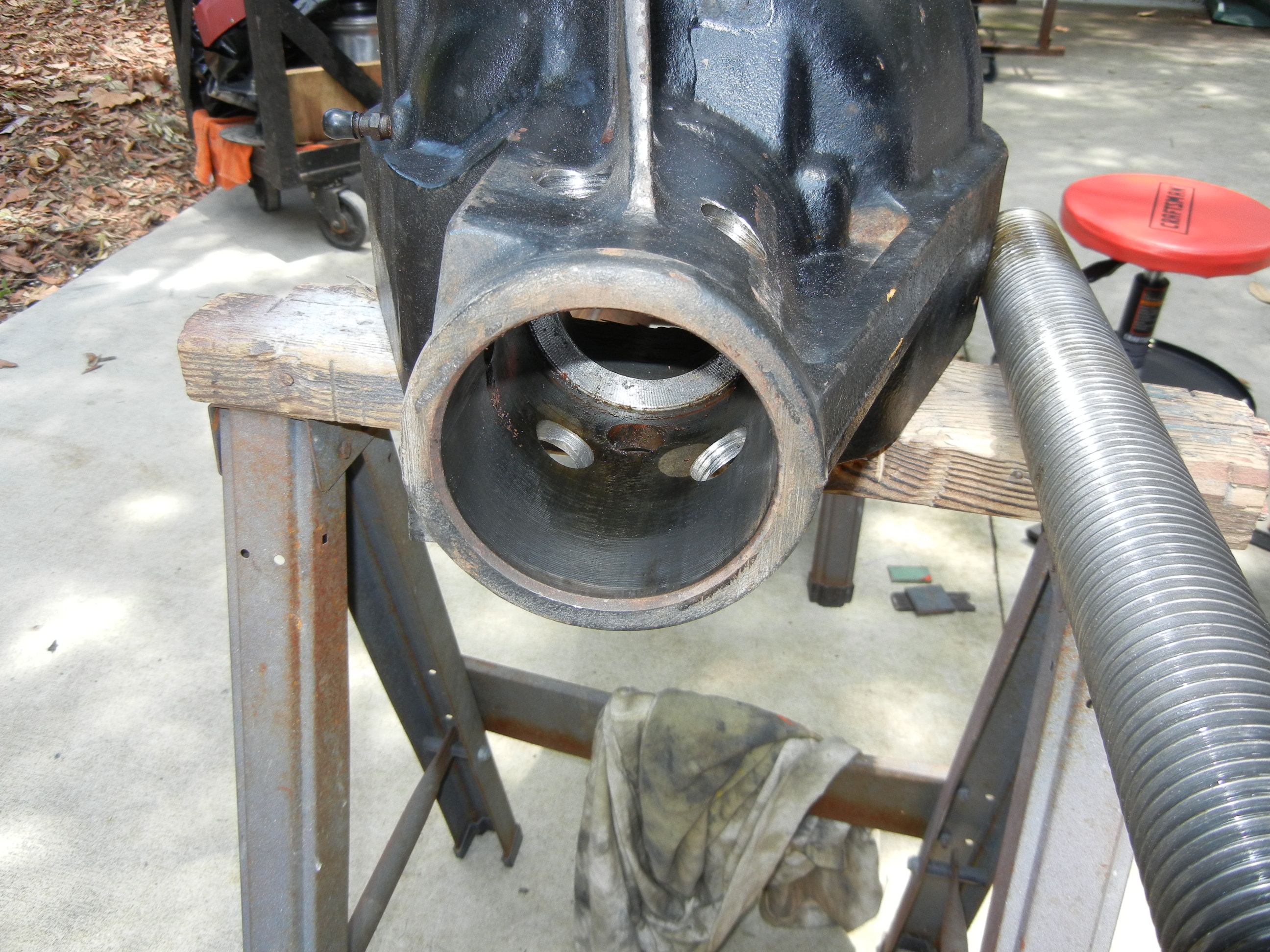
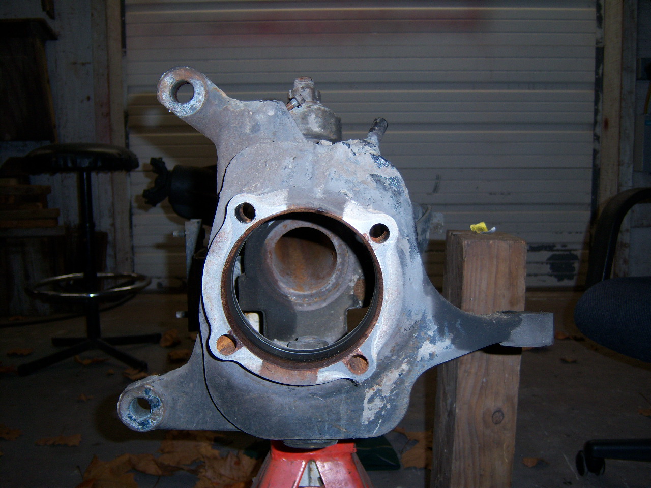
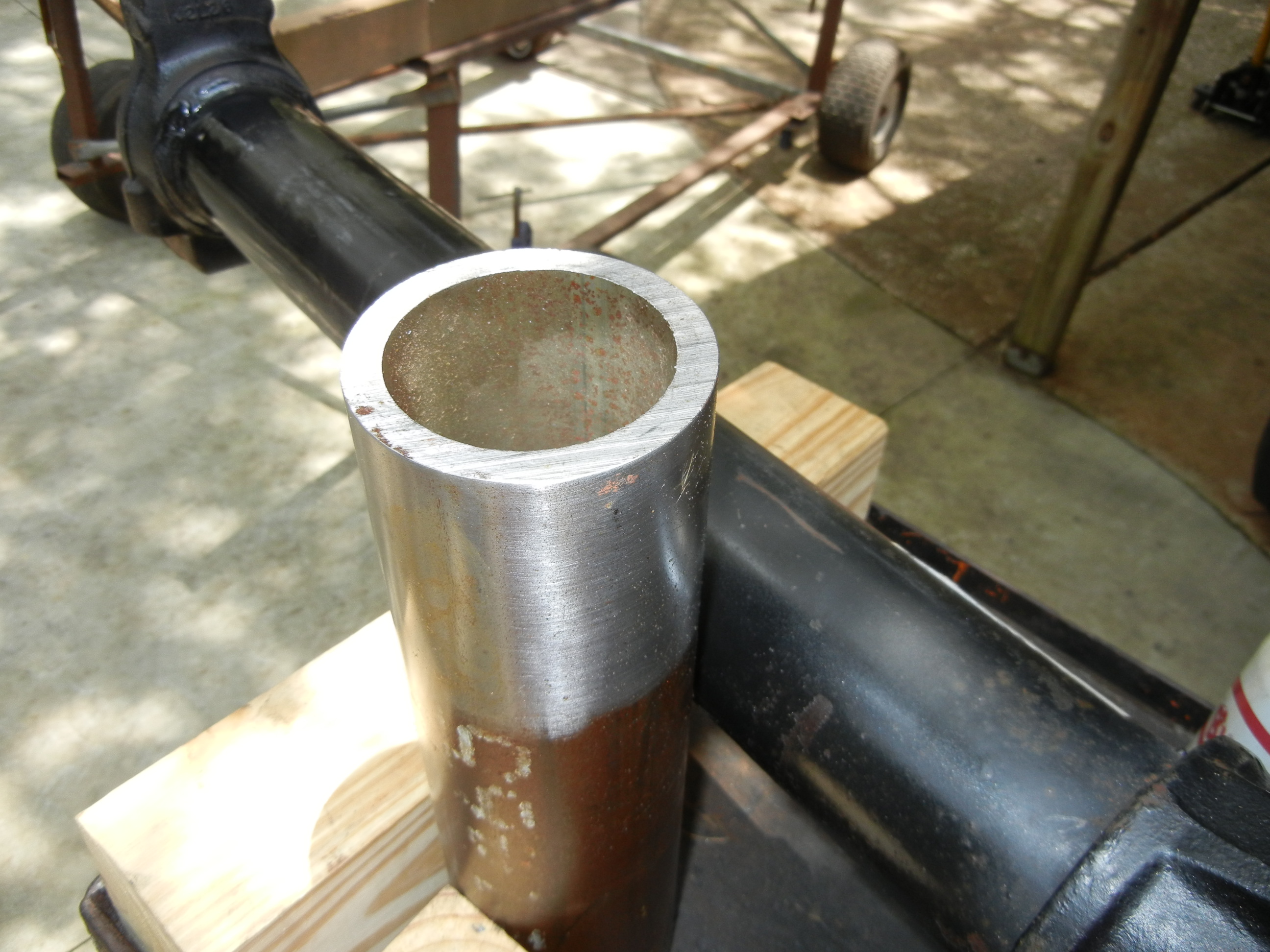
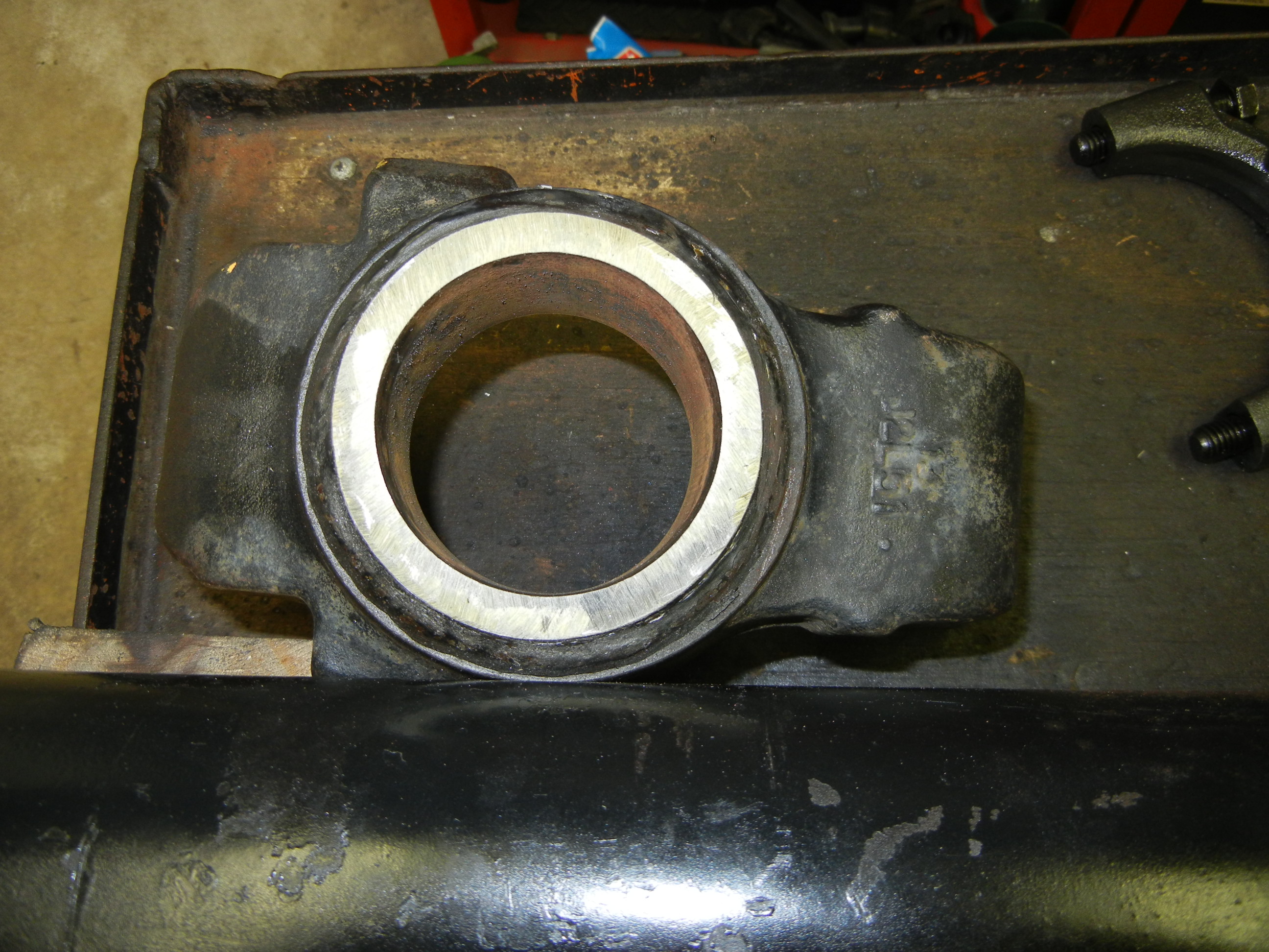
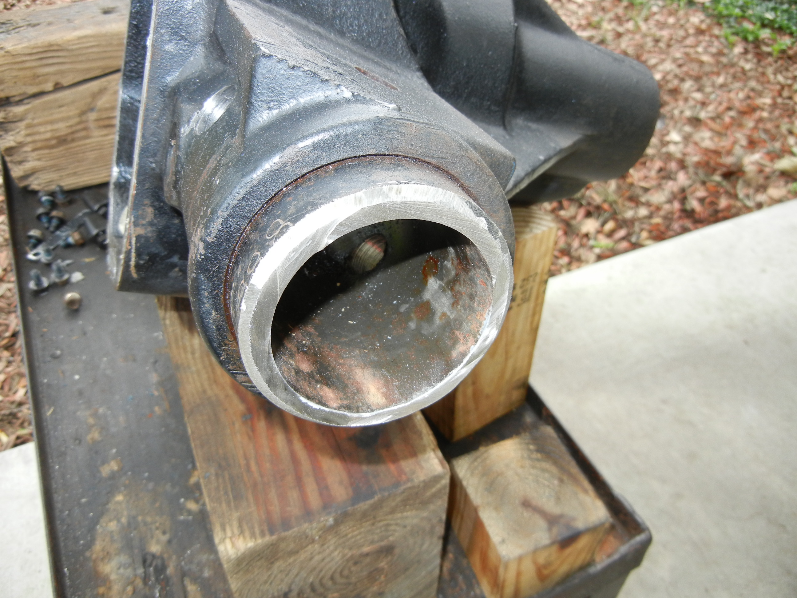
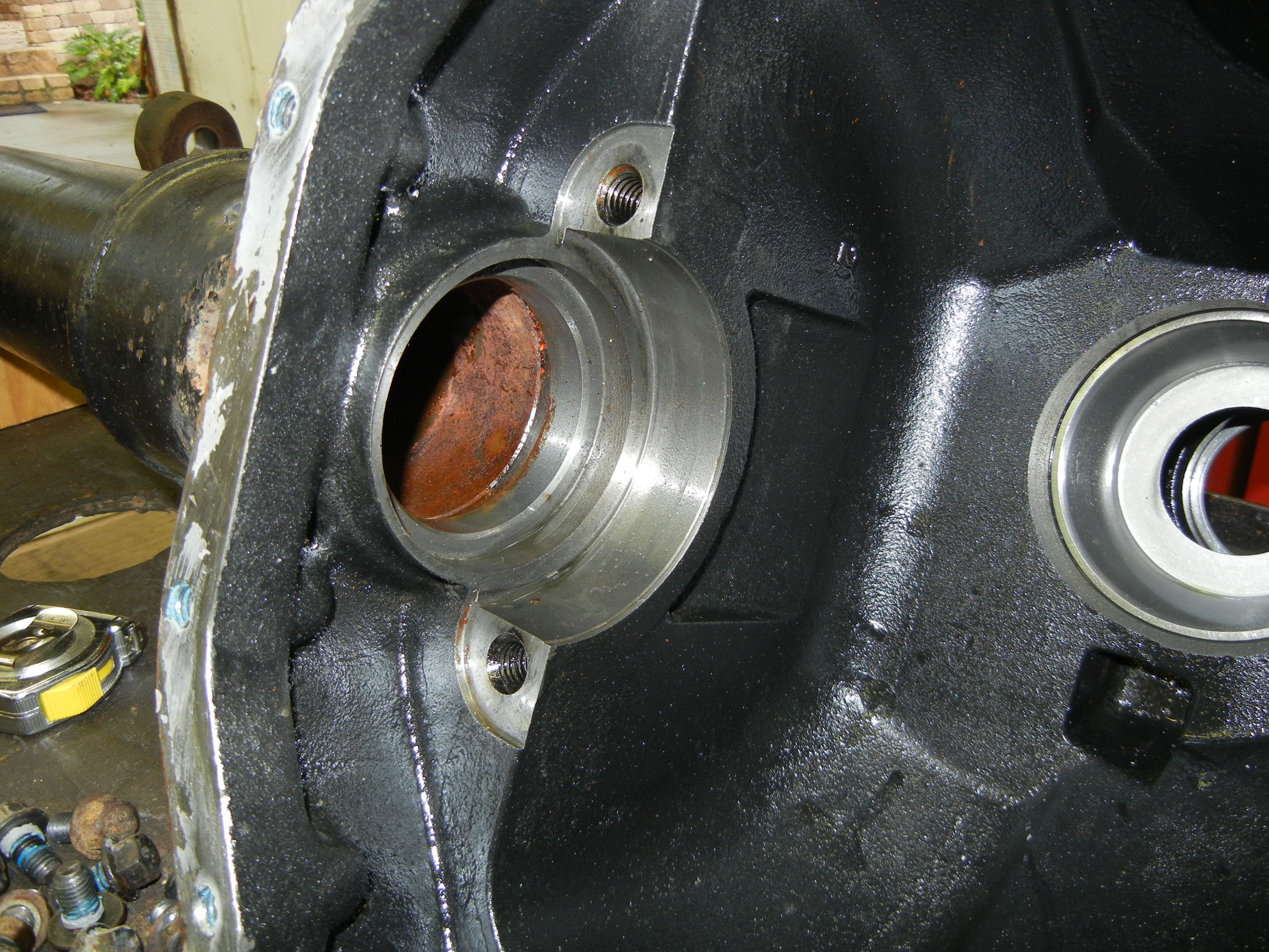
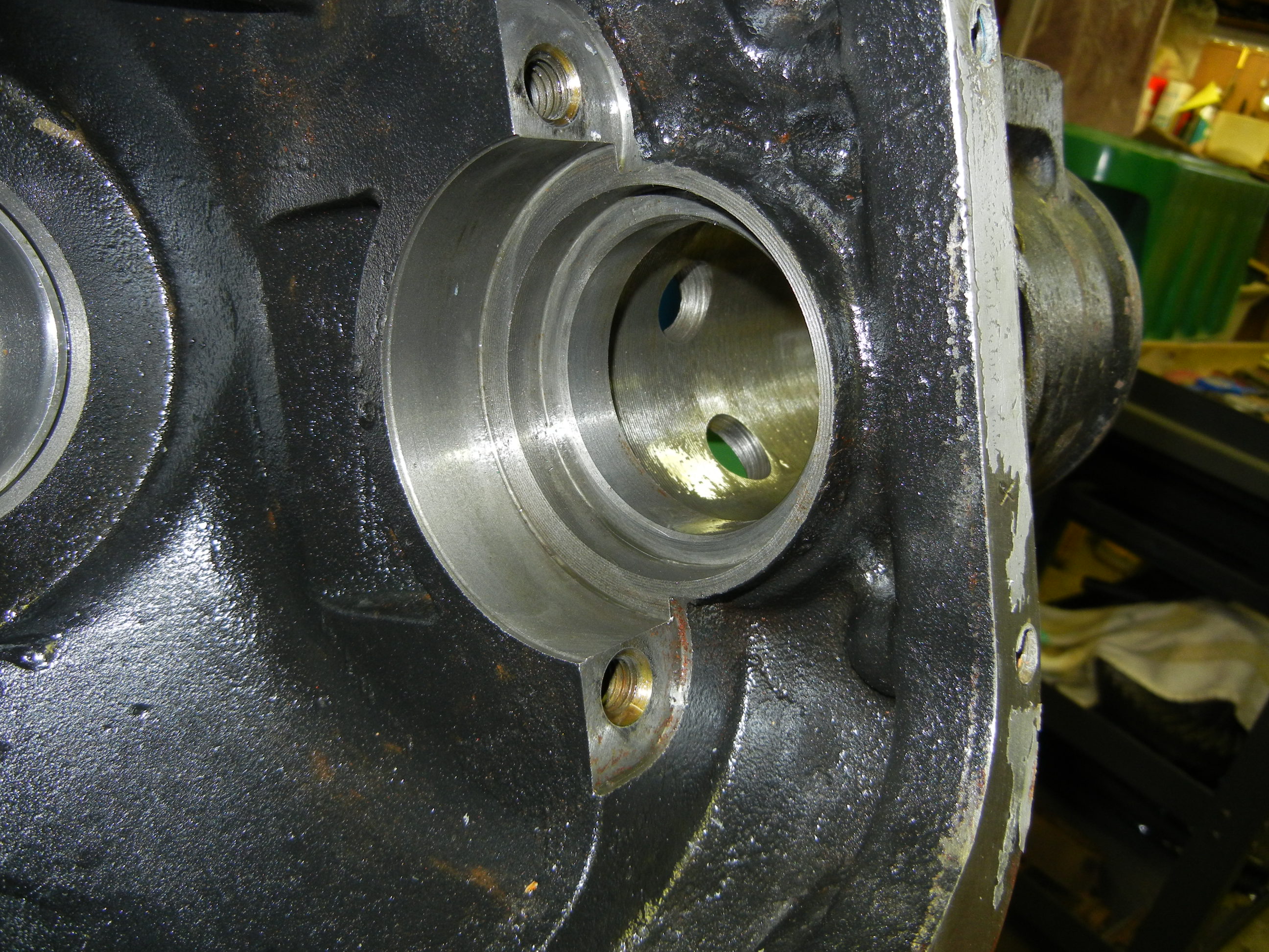
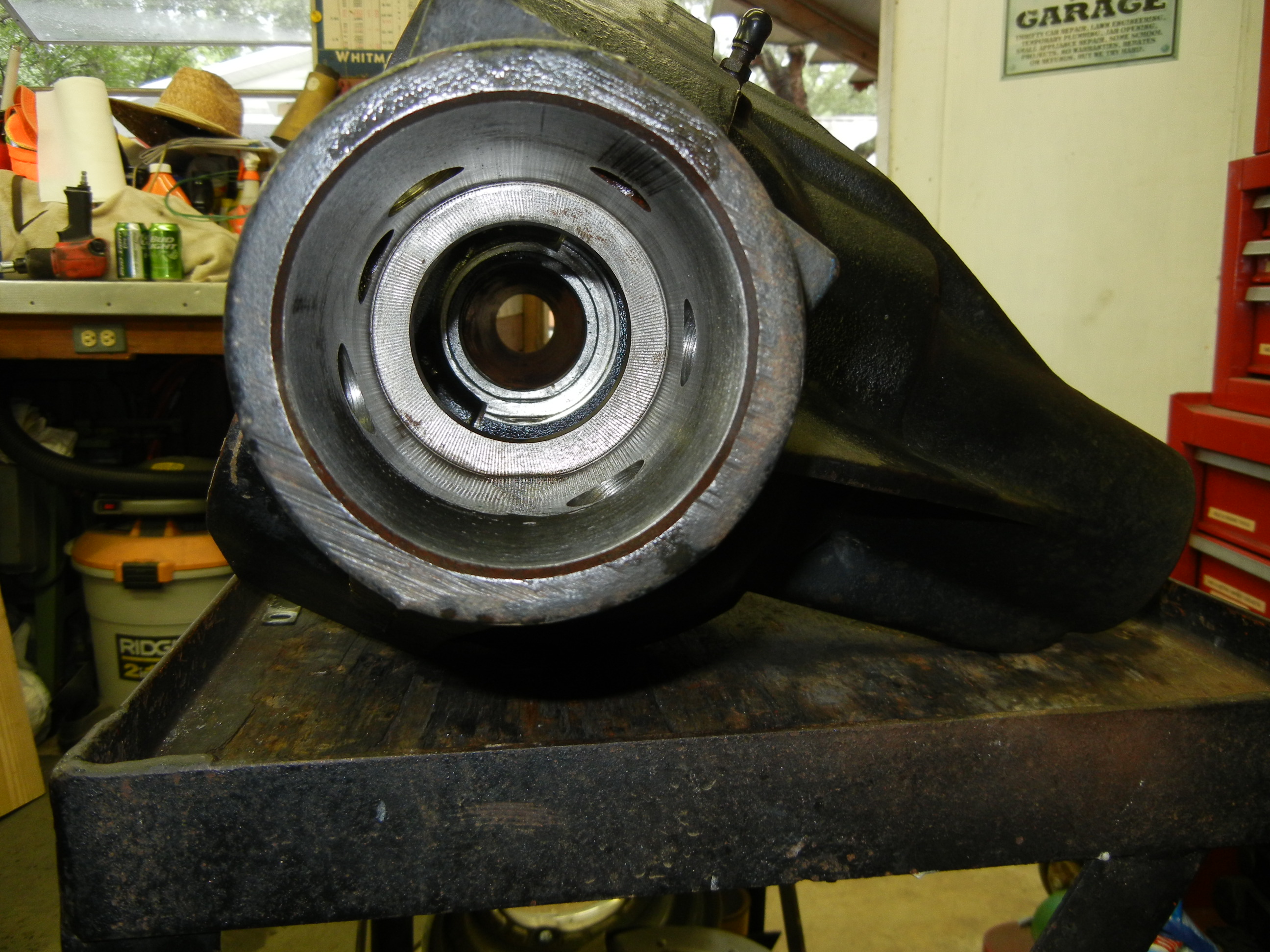
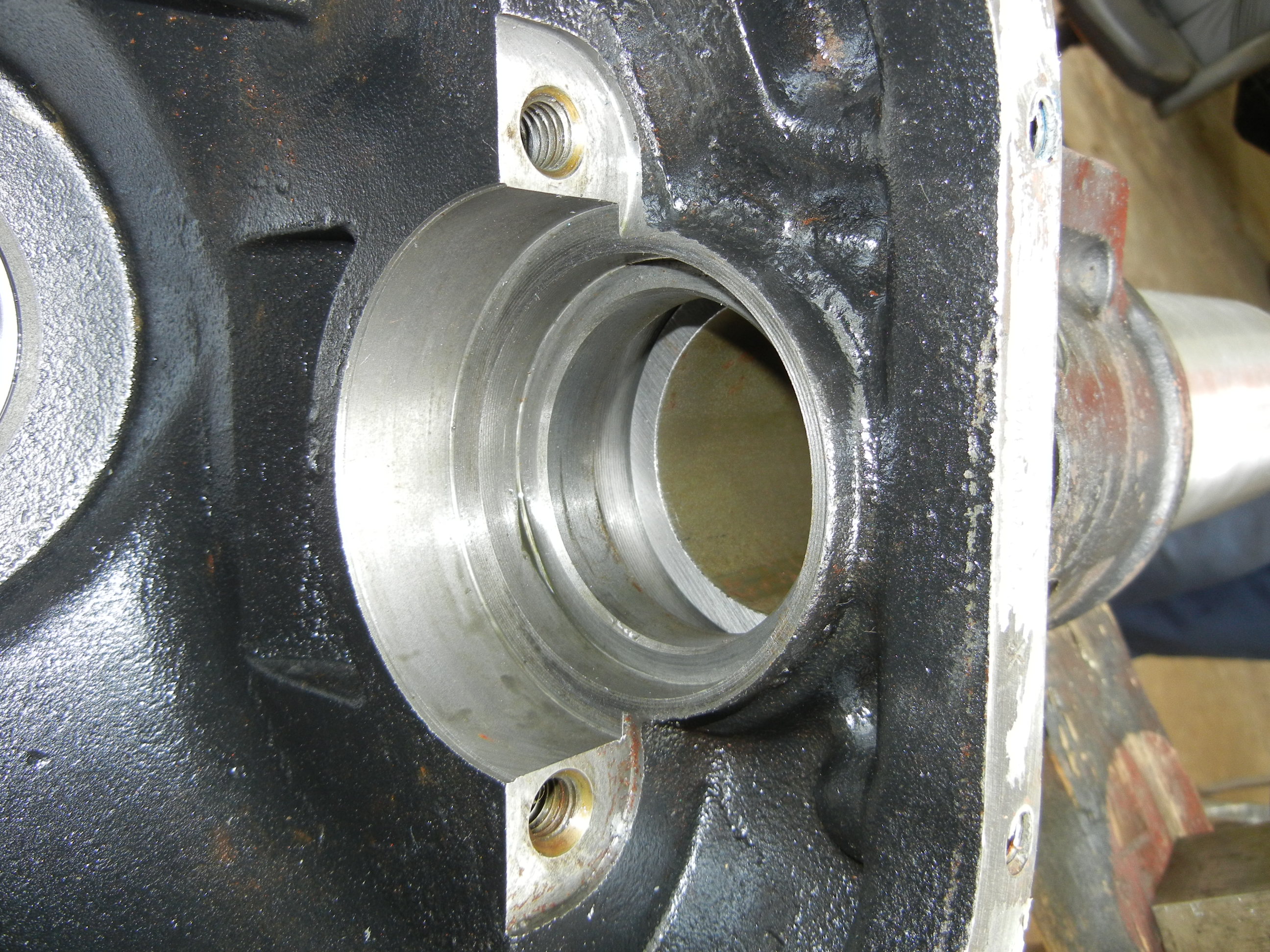
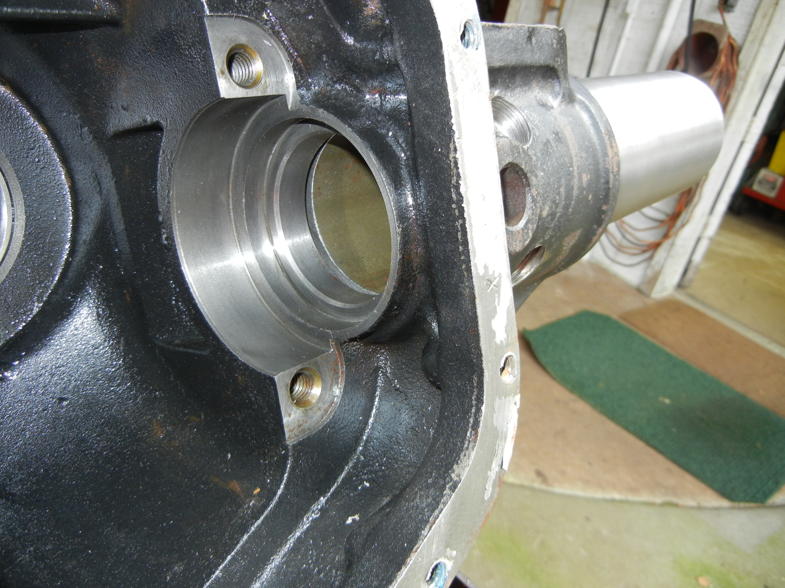
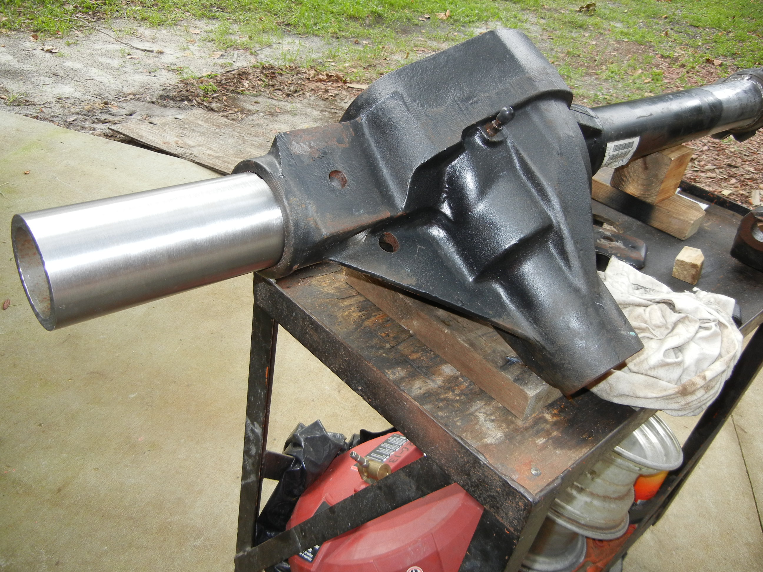
Here is the housing with the tube fully removed. The tube measured 3.502" while the housing measured 3.498" making for a 0.004" press-fit.
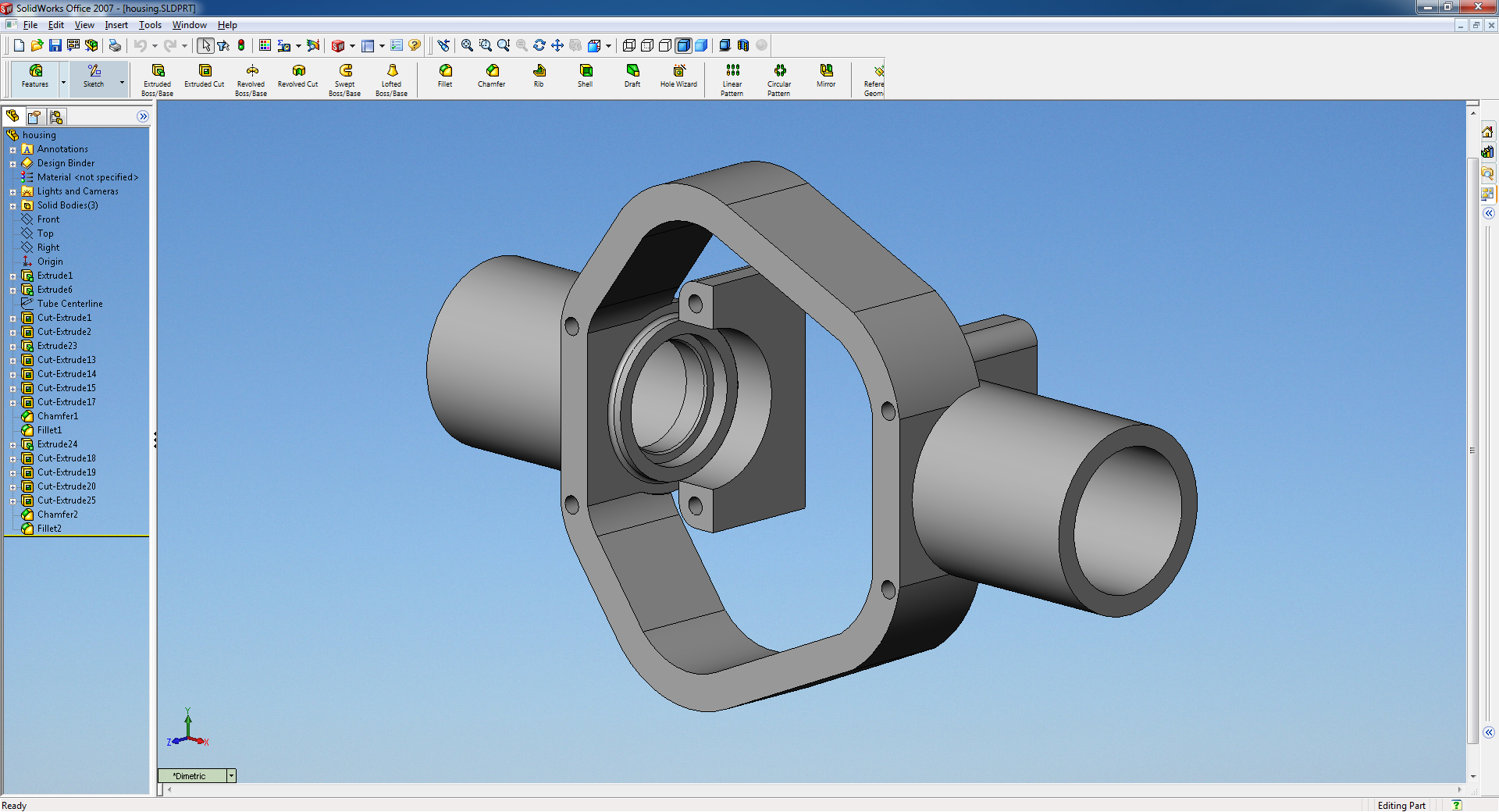
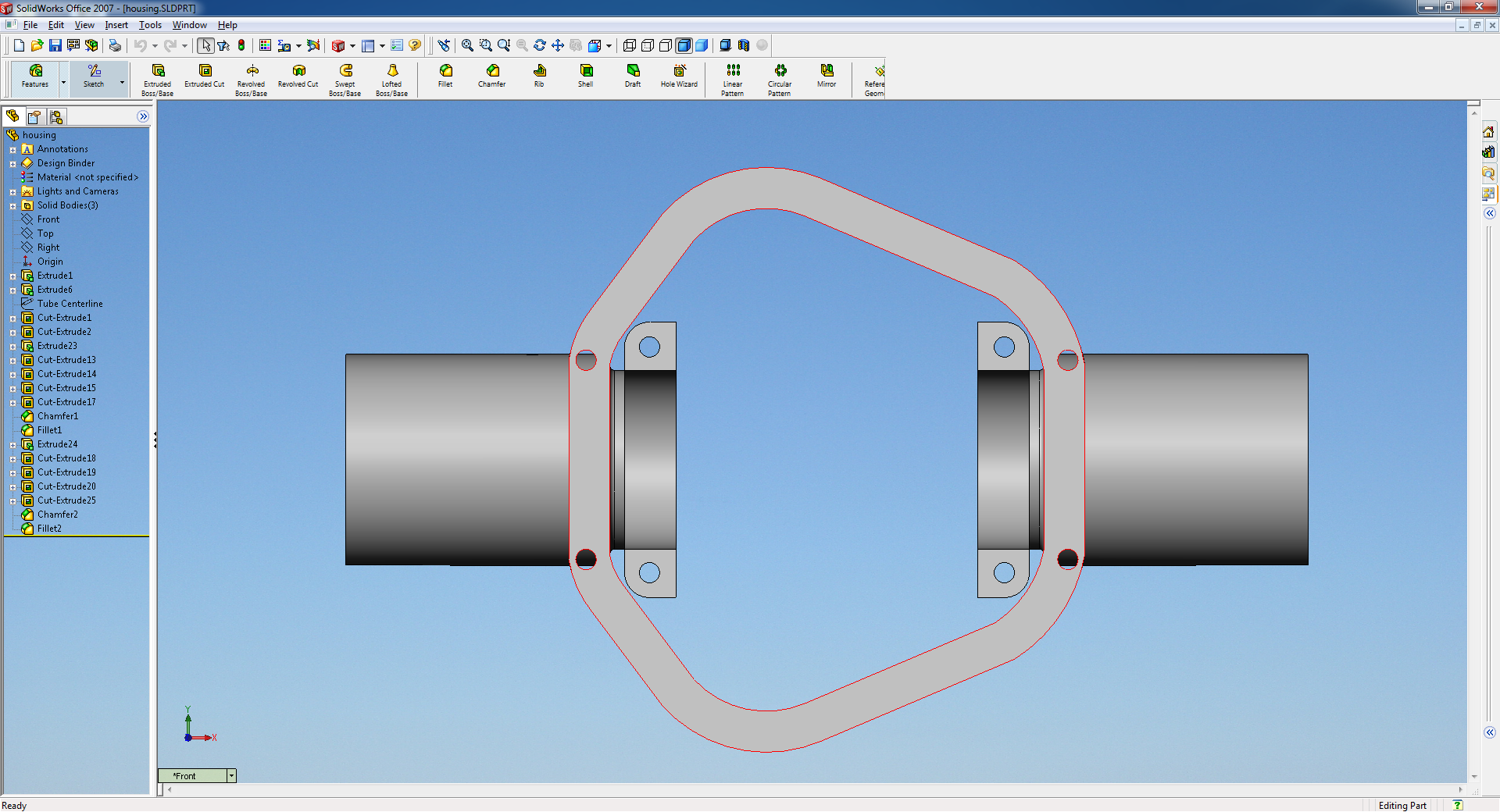
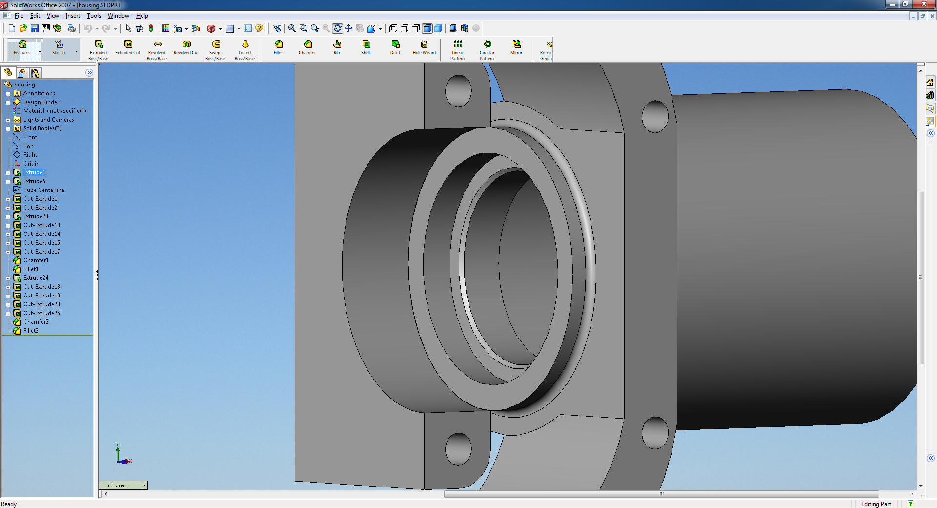
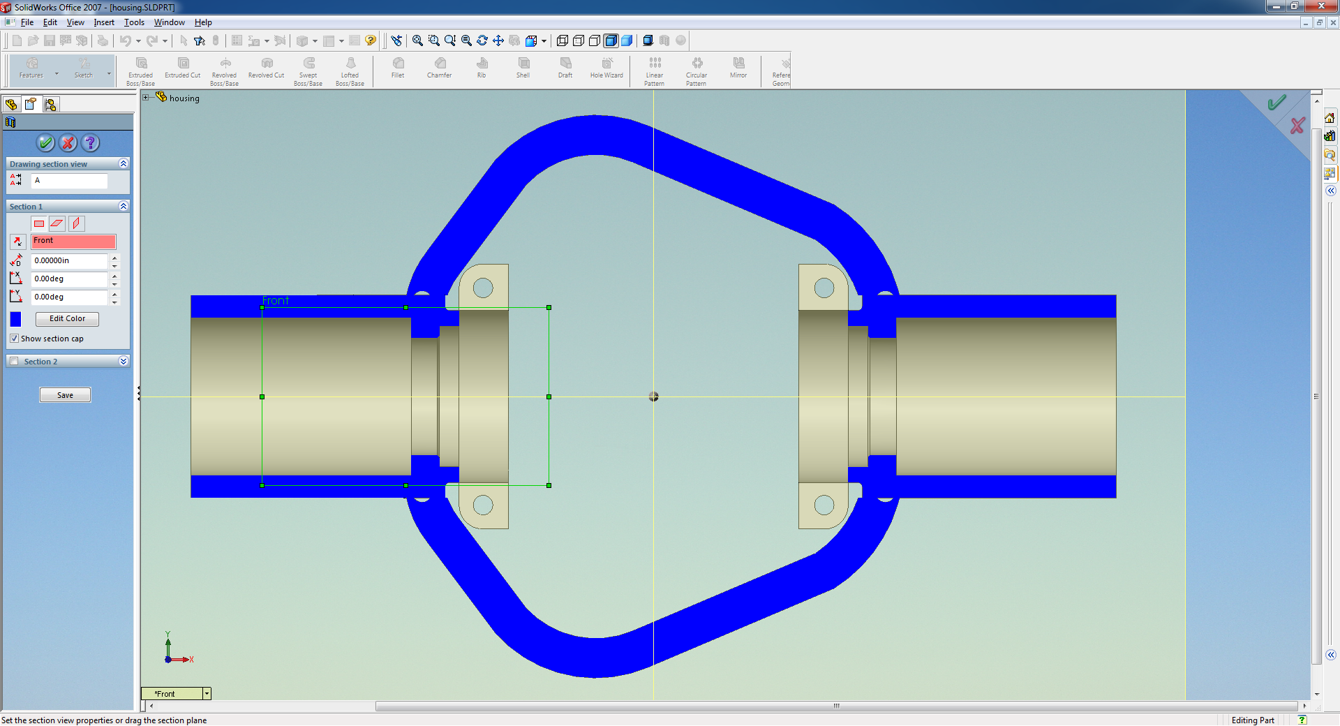
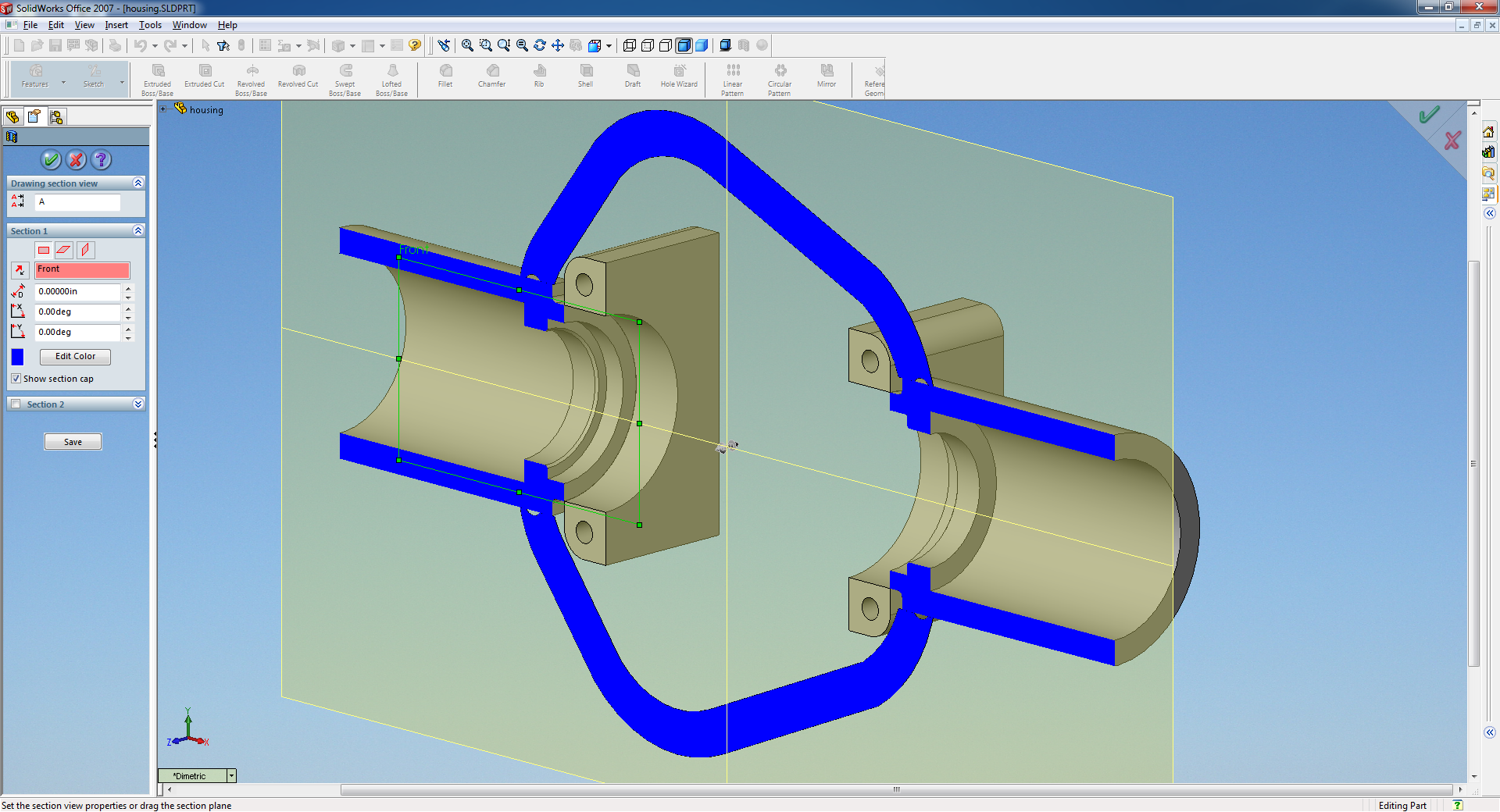
For the remaining portion of this project, I needed to model the housing to determine the tube lengths. I am not making wild suspension brackets on top of the housing or anything like that so no need to model everything exactly, just the inner bearing caps and the overall shape/length of the center section. More on this later!
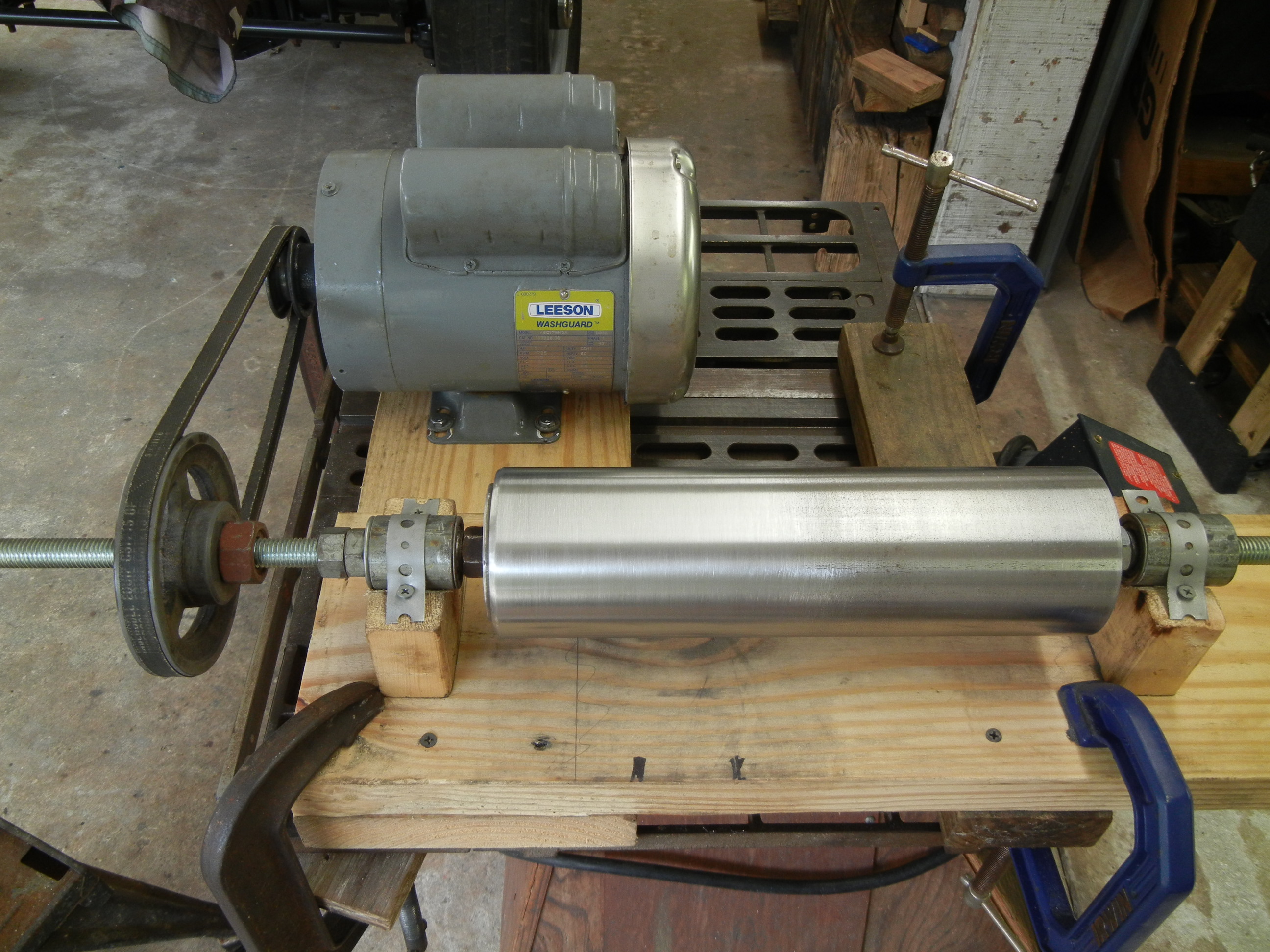
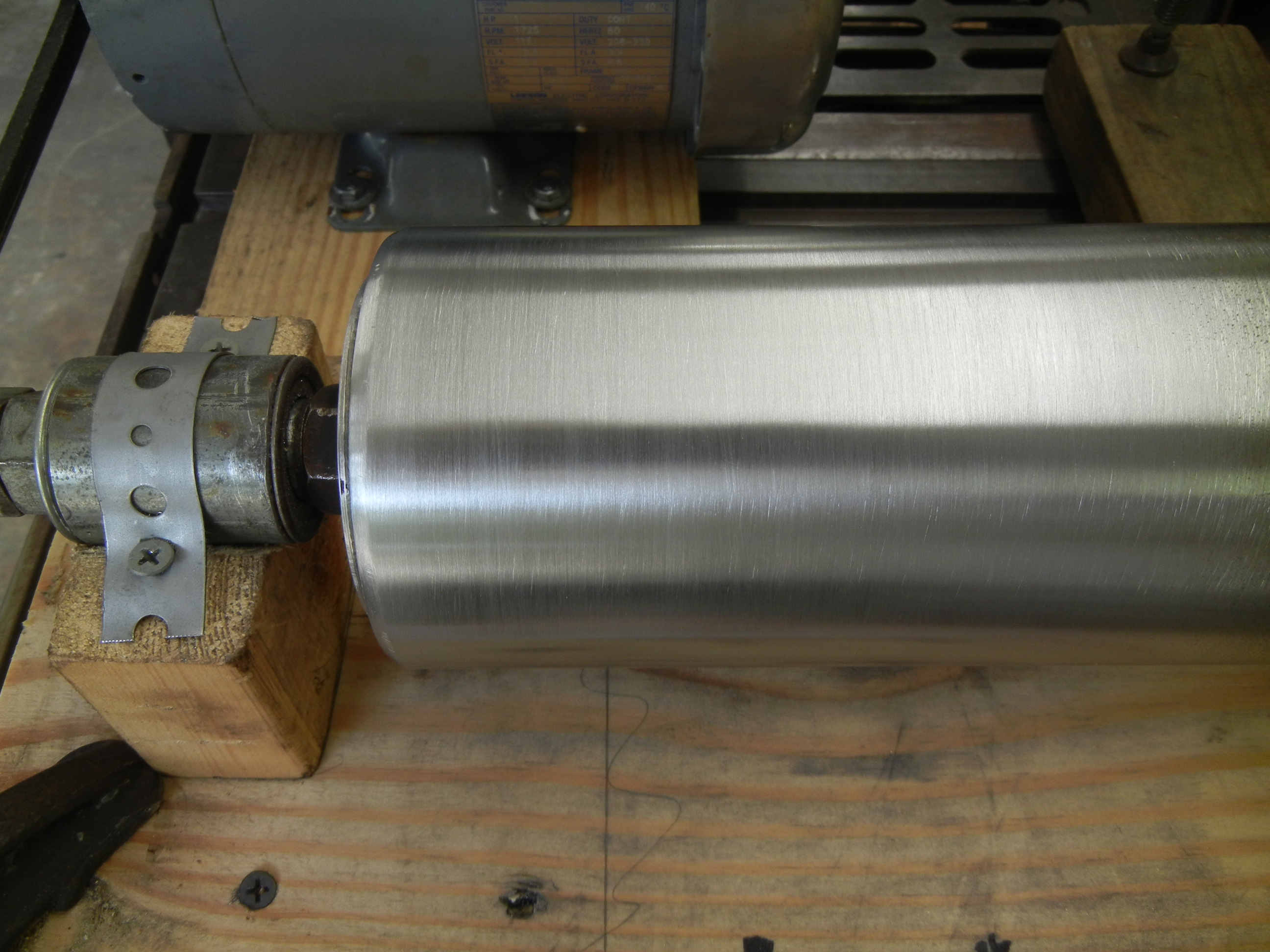
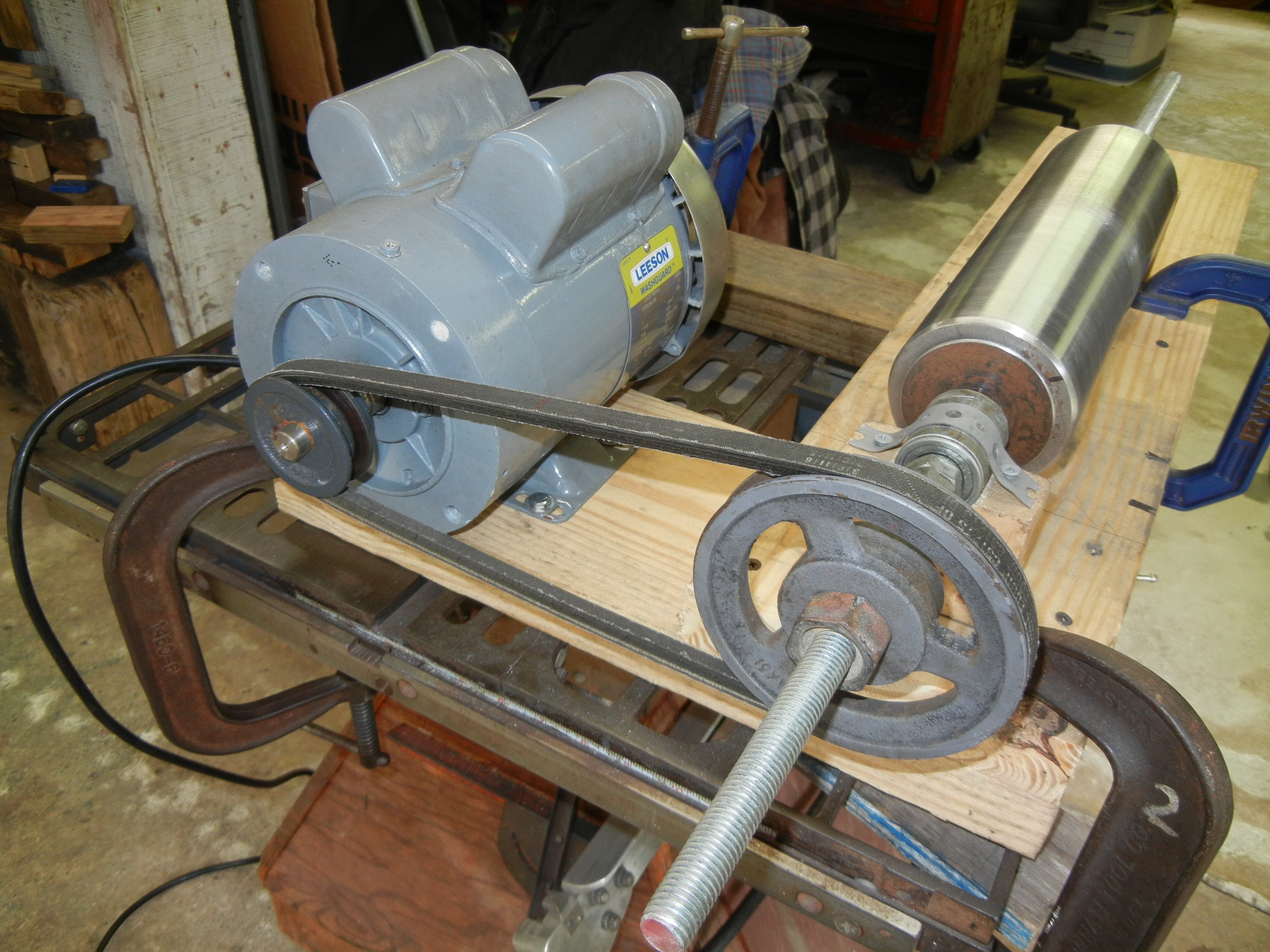
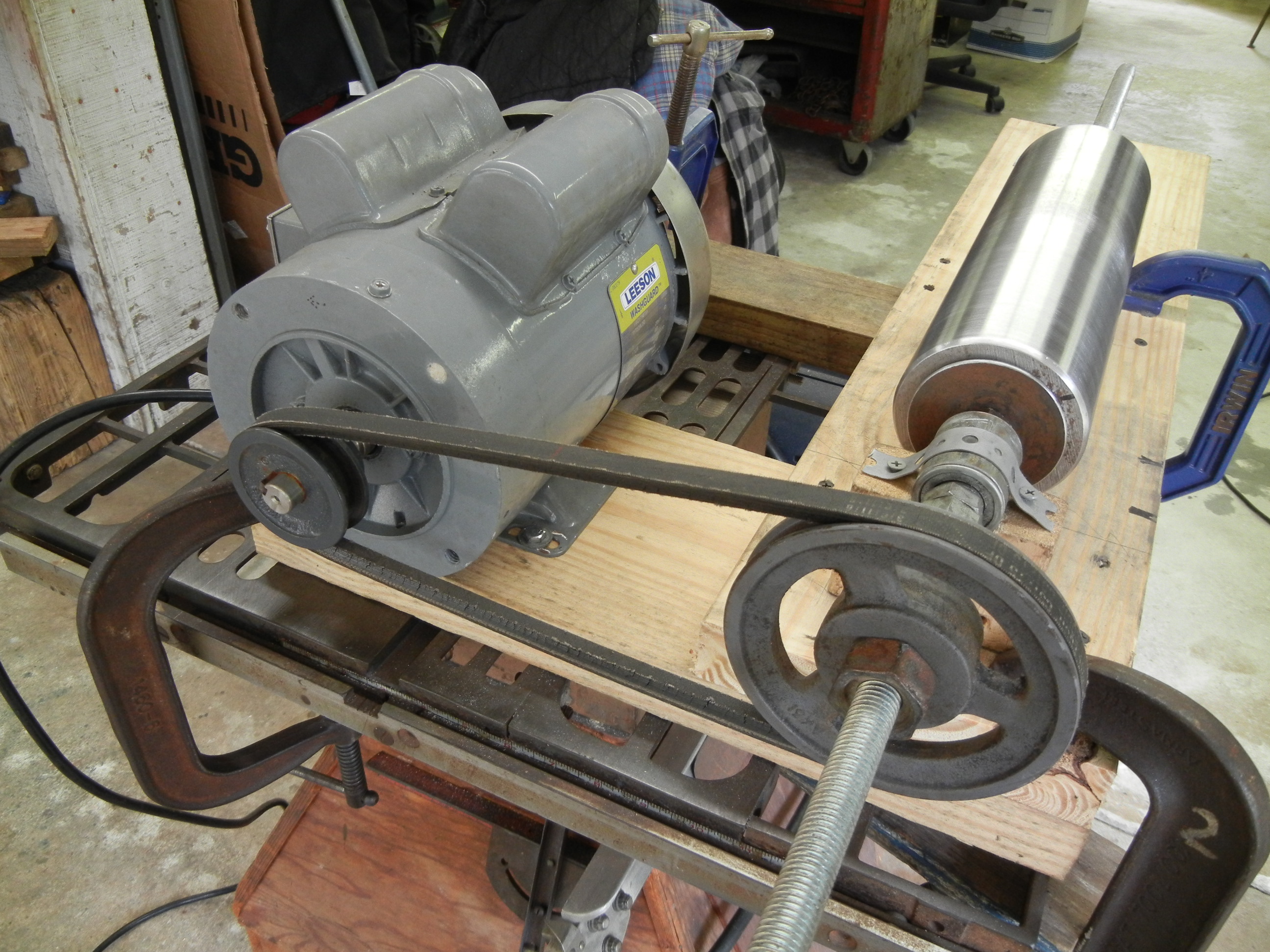
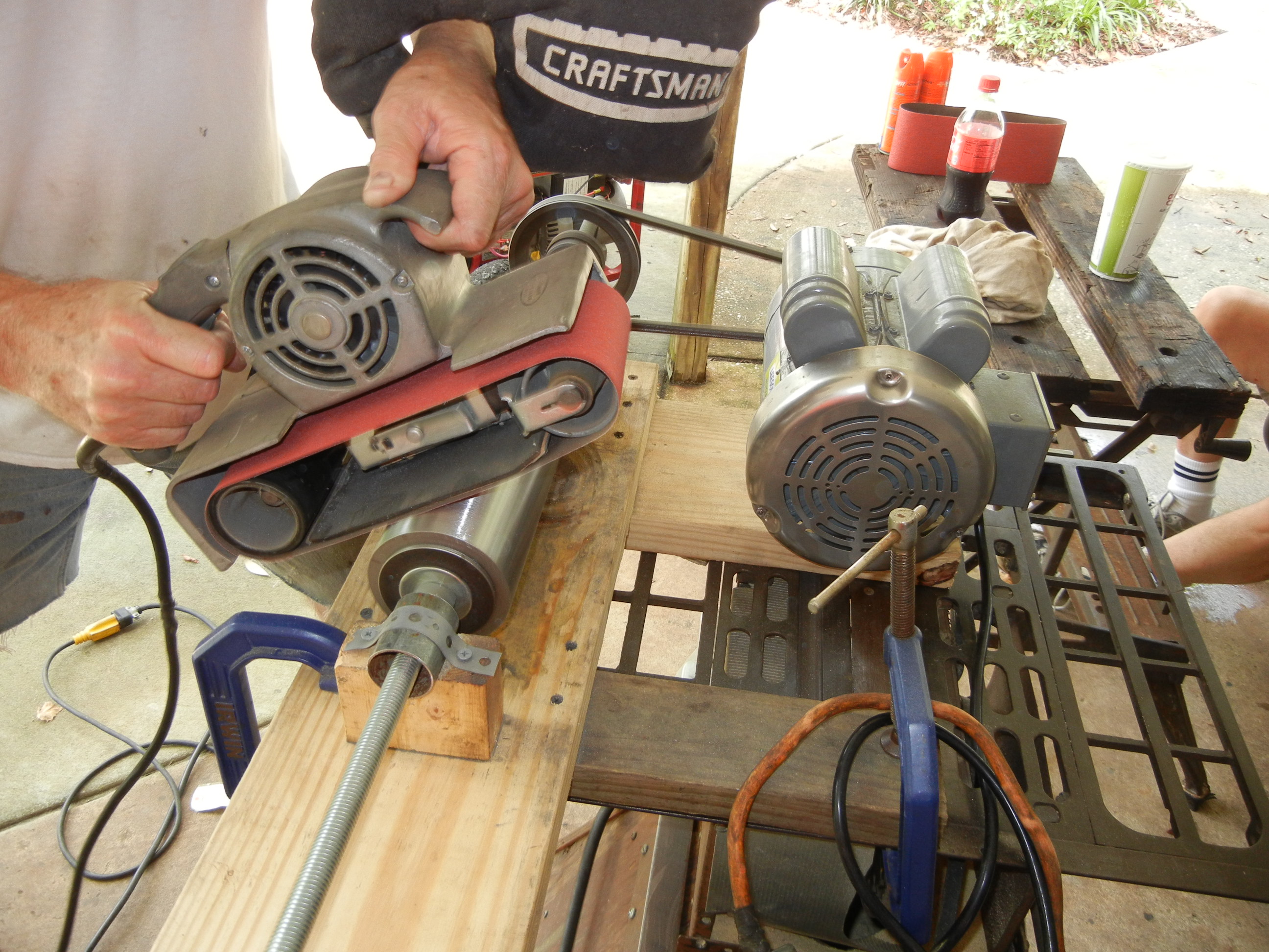
Not needing to turn the tube diameter down much, we decided we could do this on our own. Plus we wanted to prove it could be done at home without the need of a machine shop (remember the Sterling's disc conversion?)! As any true machinist knows- start from the inside and work outwards. The tube was very true on the inside so my father made some spacers to attach the threaded rod and after giving it a spin only then could you see the OD wobble ever so slightly. The motor is a 1750rpm to keep the speed down while a belt sander removed just the right amount.
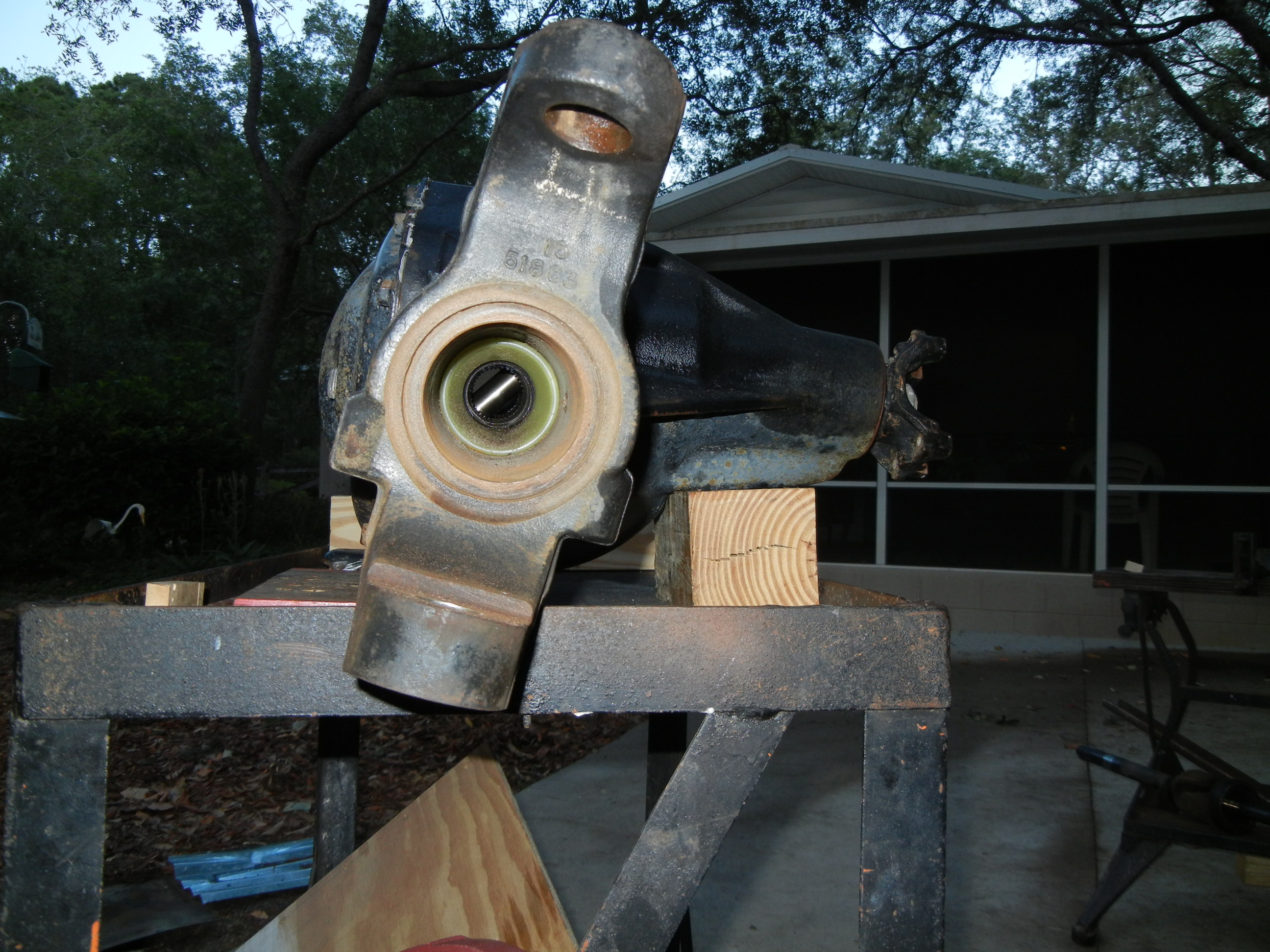
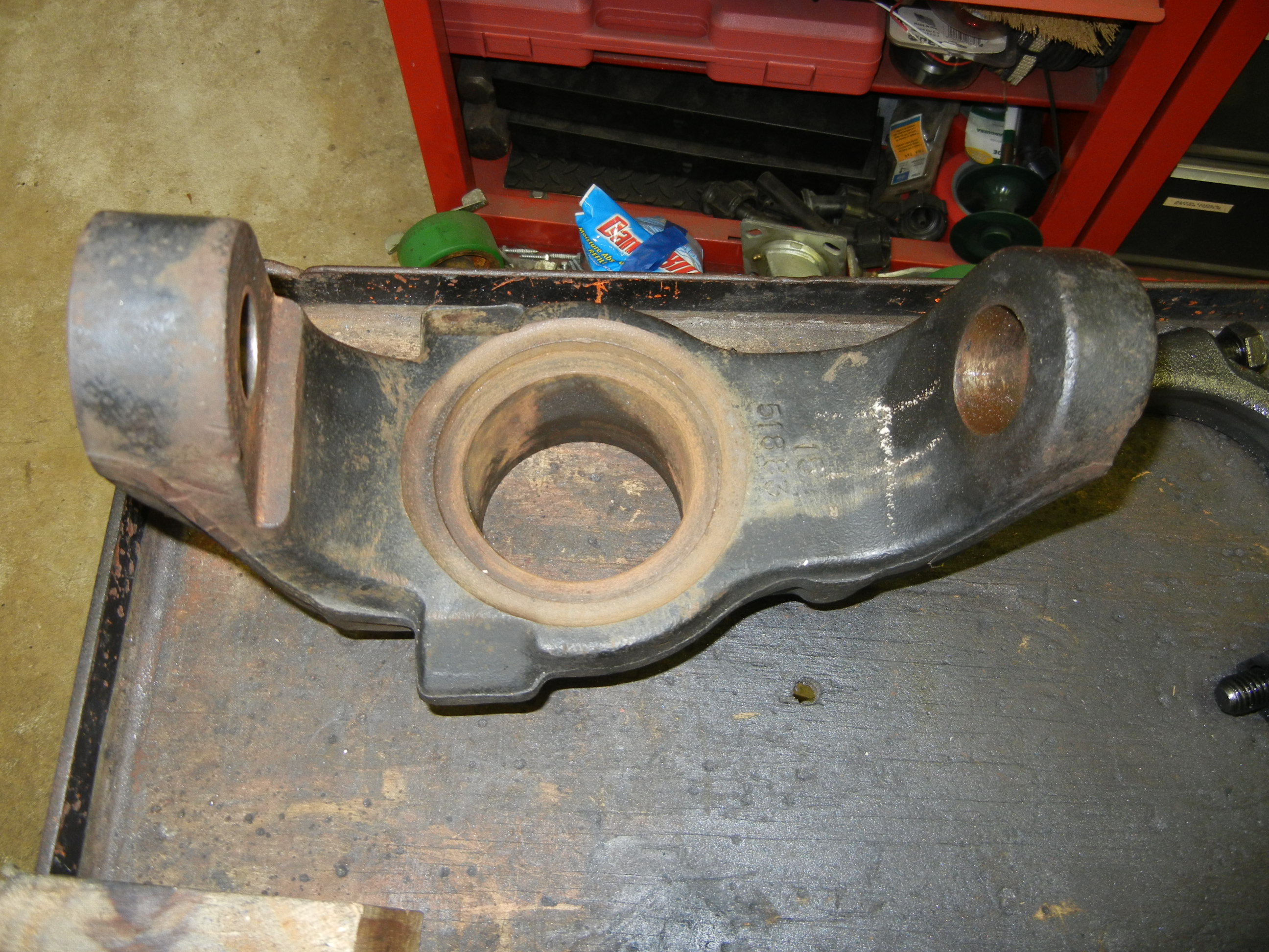
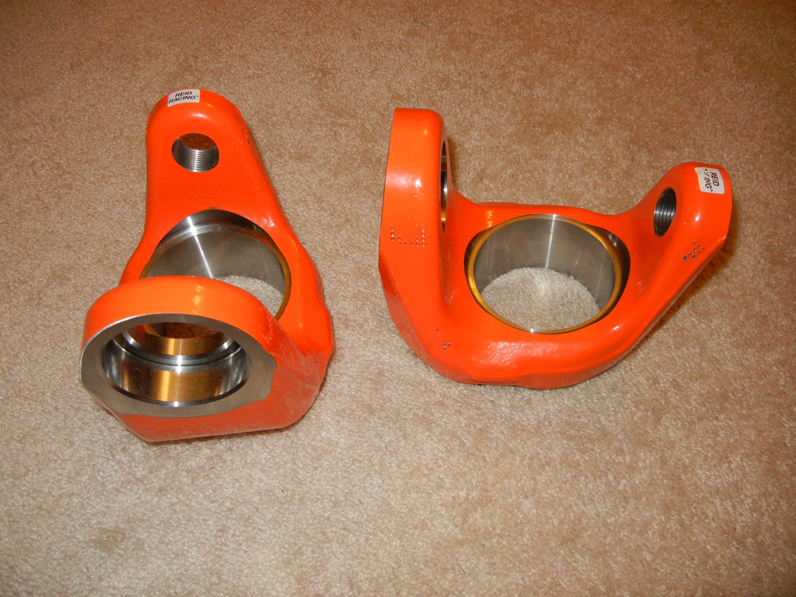
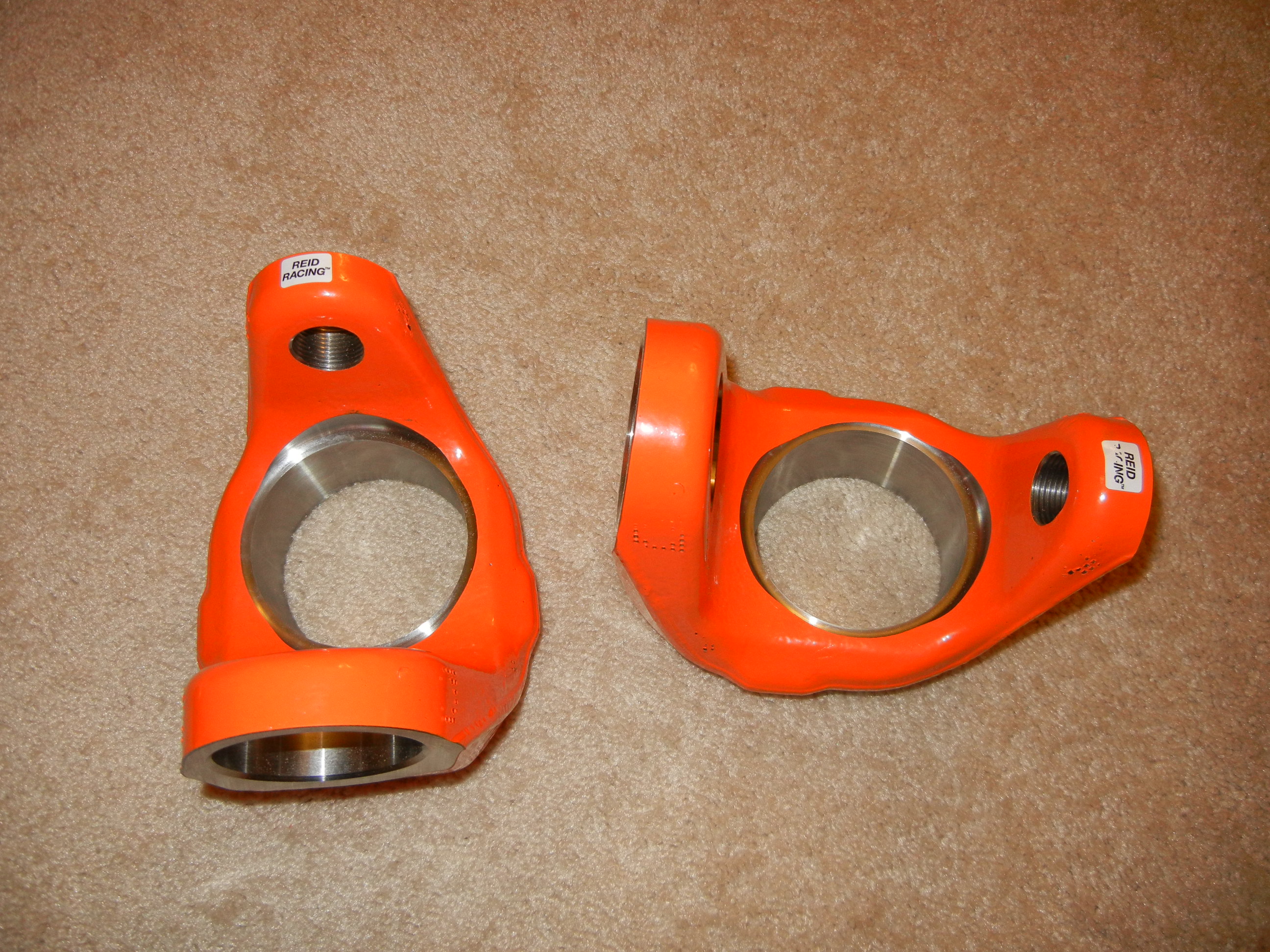
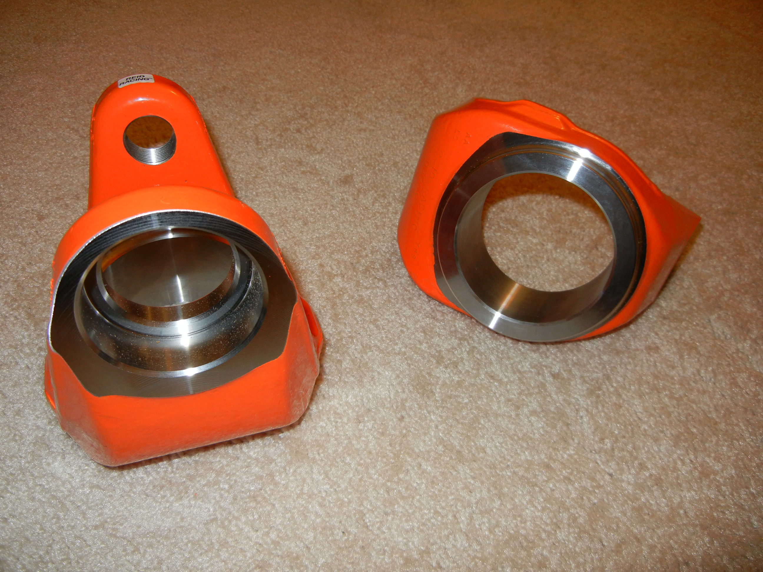
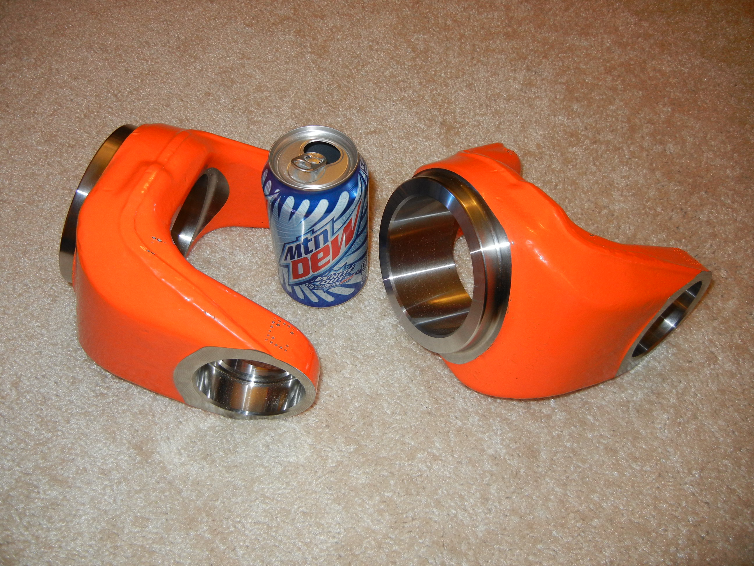
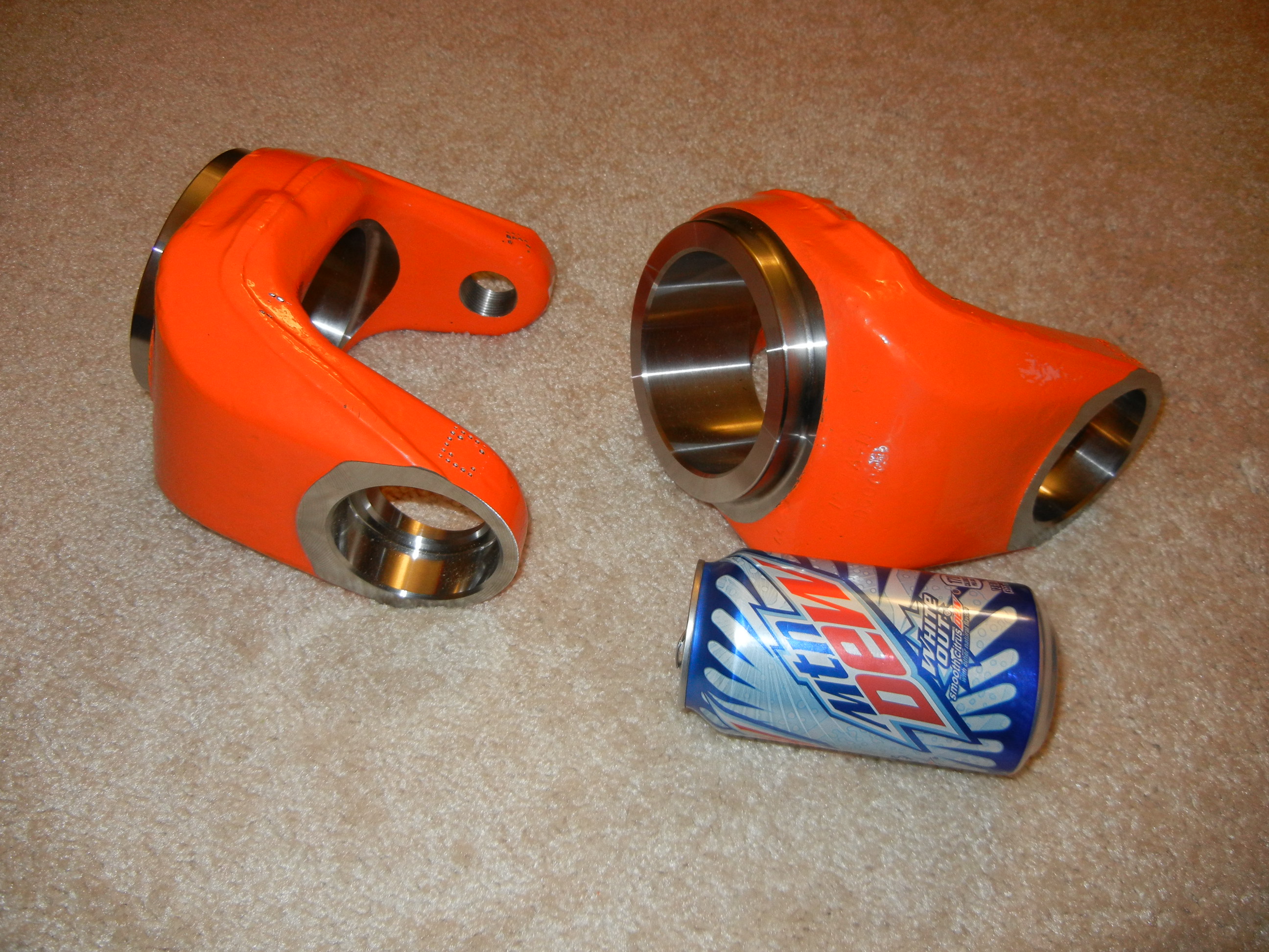
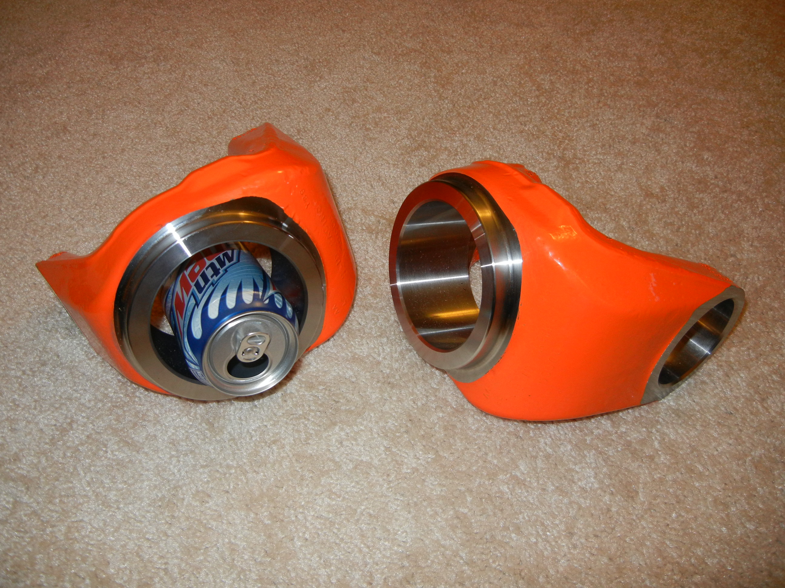
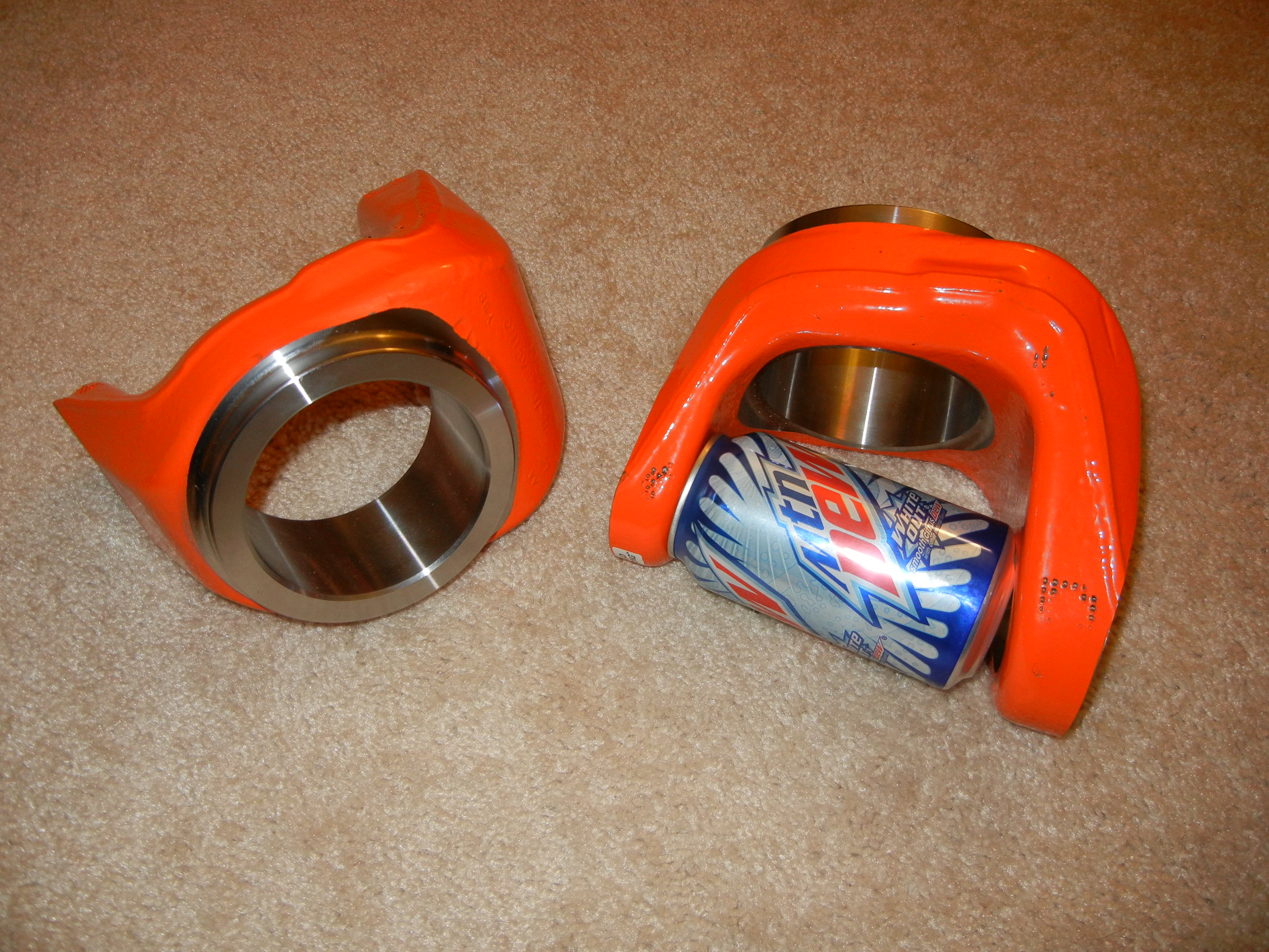
Well the beefy Reid inner C's finally showed up! They truly are works of art! For the price of these things I seriously considered the Solid Axle Industries' version, but after discovering those only come with a 3" bore and would have to be machined larger, the Reid's just seemed like the way to go (same thing goes for Crane High Clearance) to keep from investing another labor expense. Plus the Reid's are made in USA! I do not know where the Solids are made. LetzRoll Offroad out of Mesa, AZ hooked me up with a great deal on these.
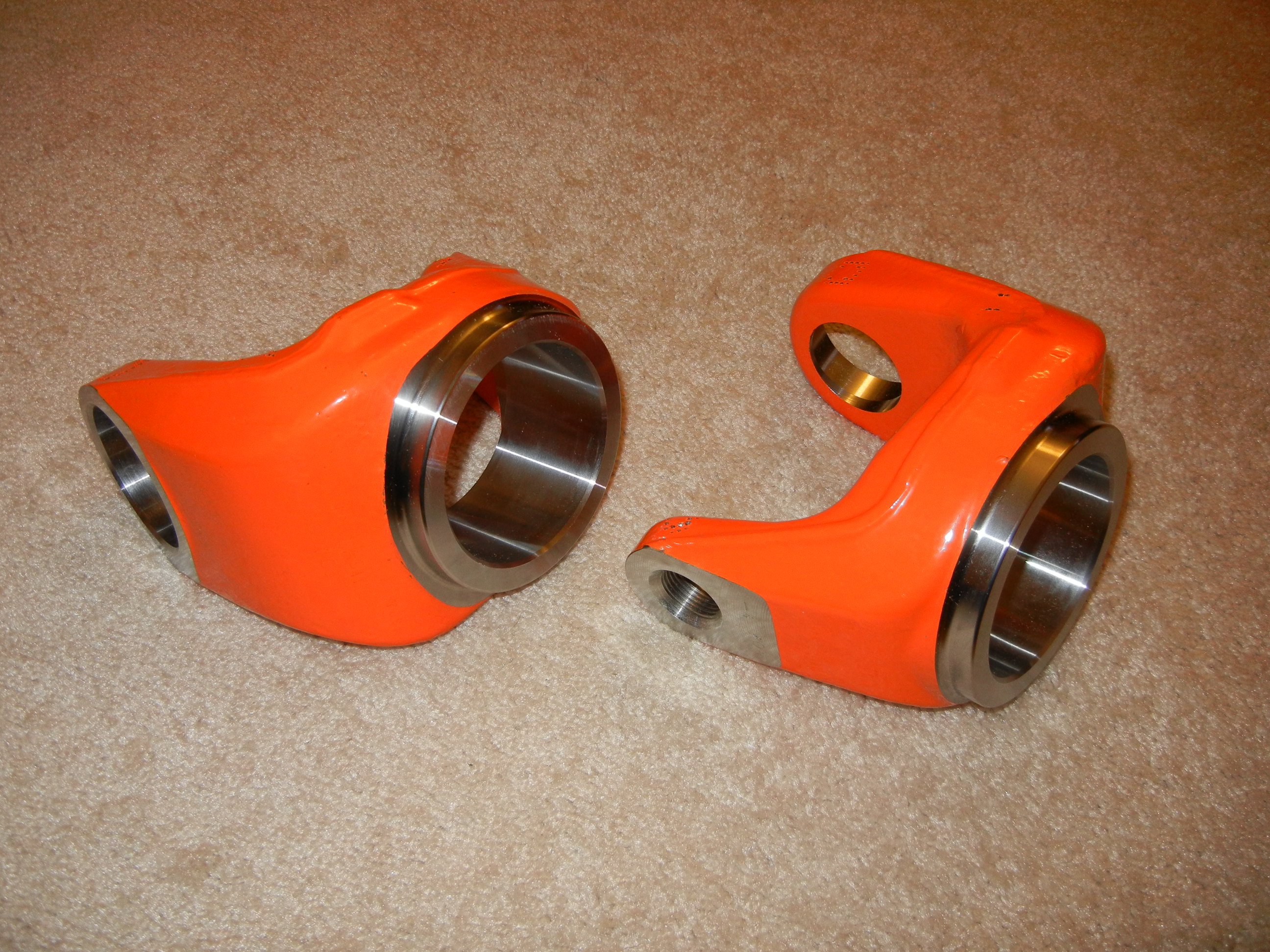
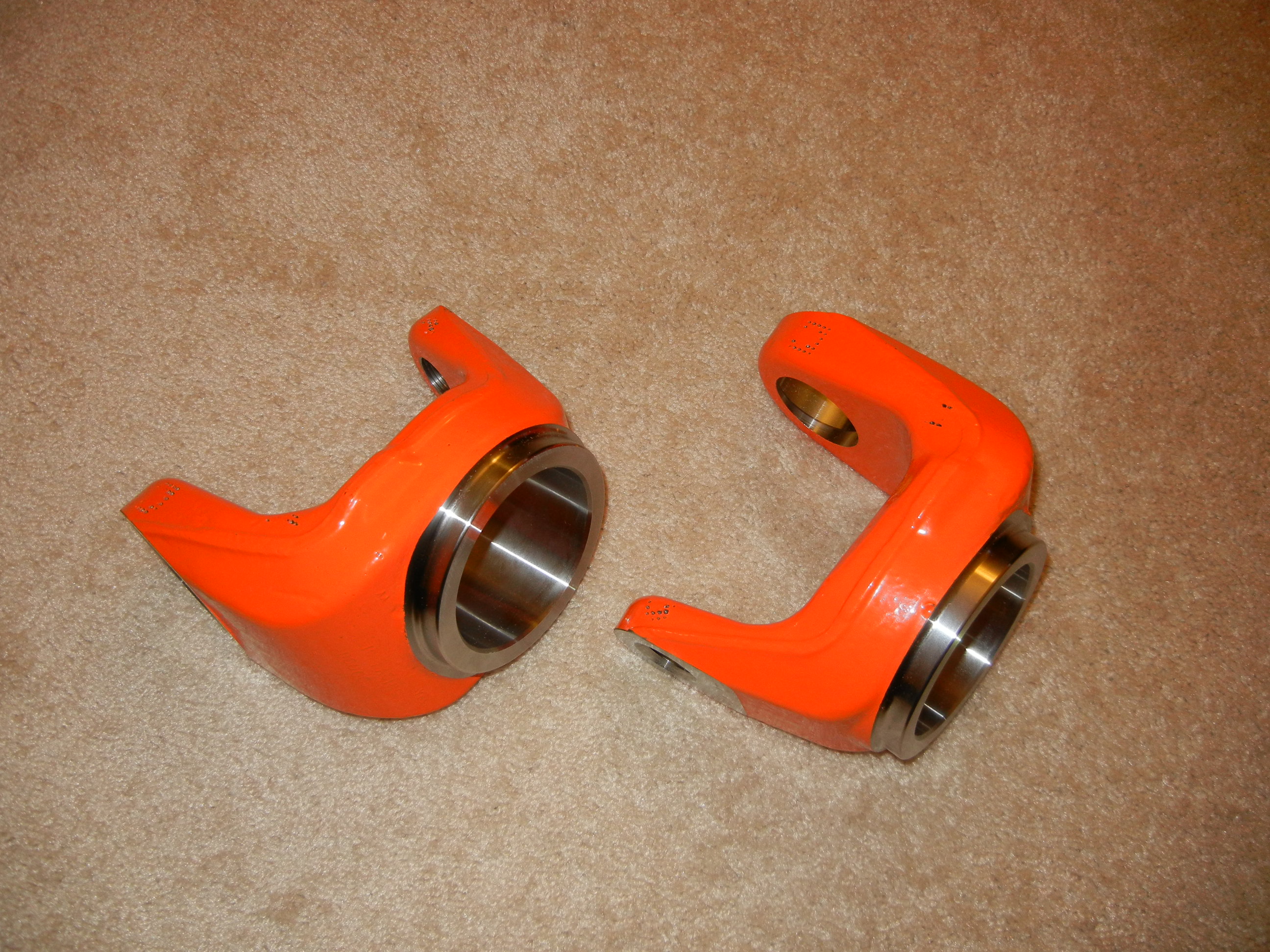
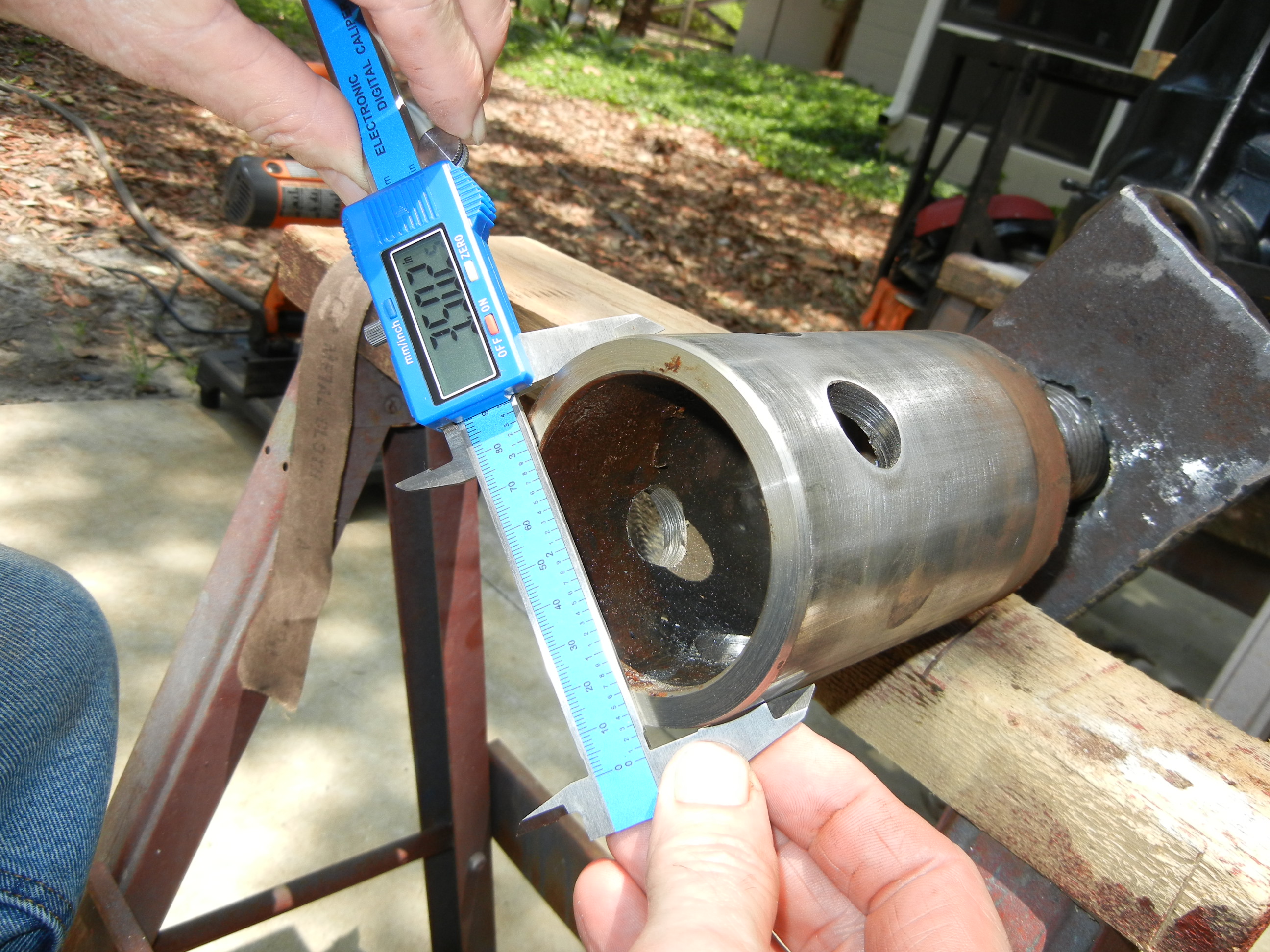
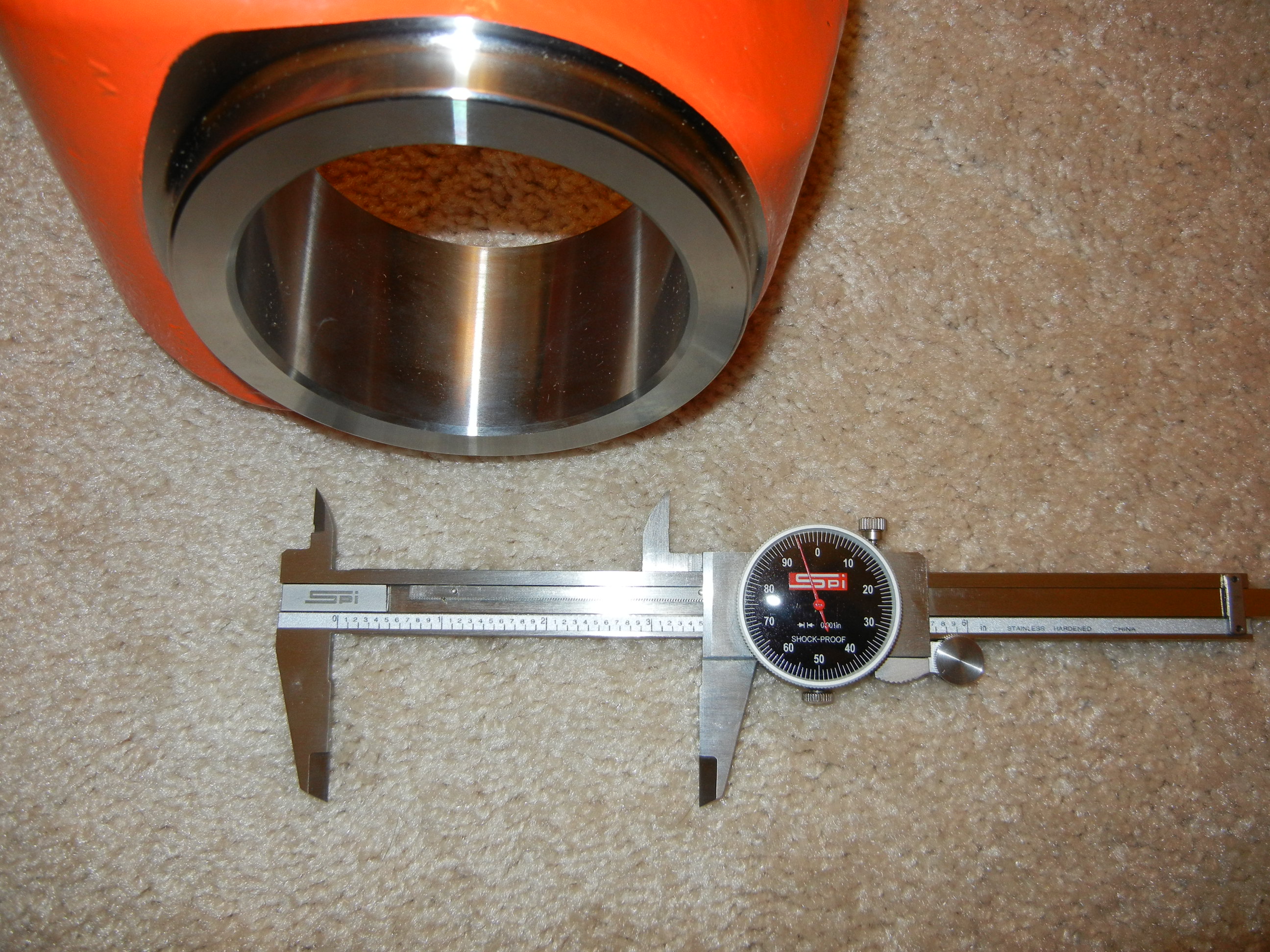
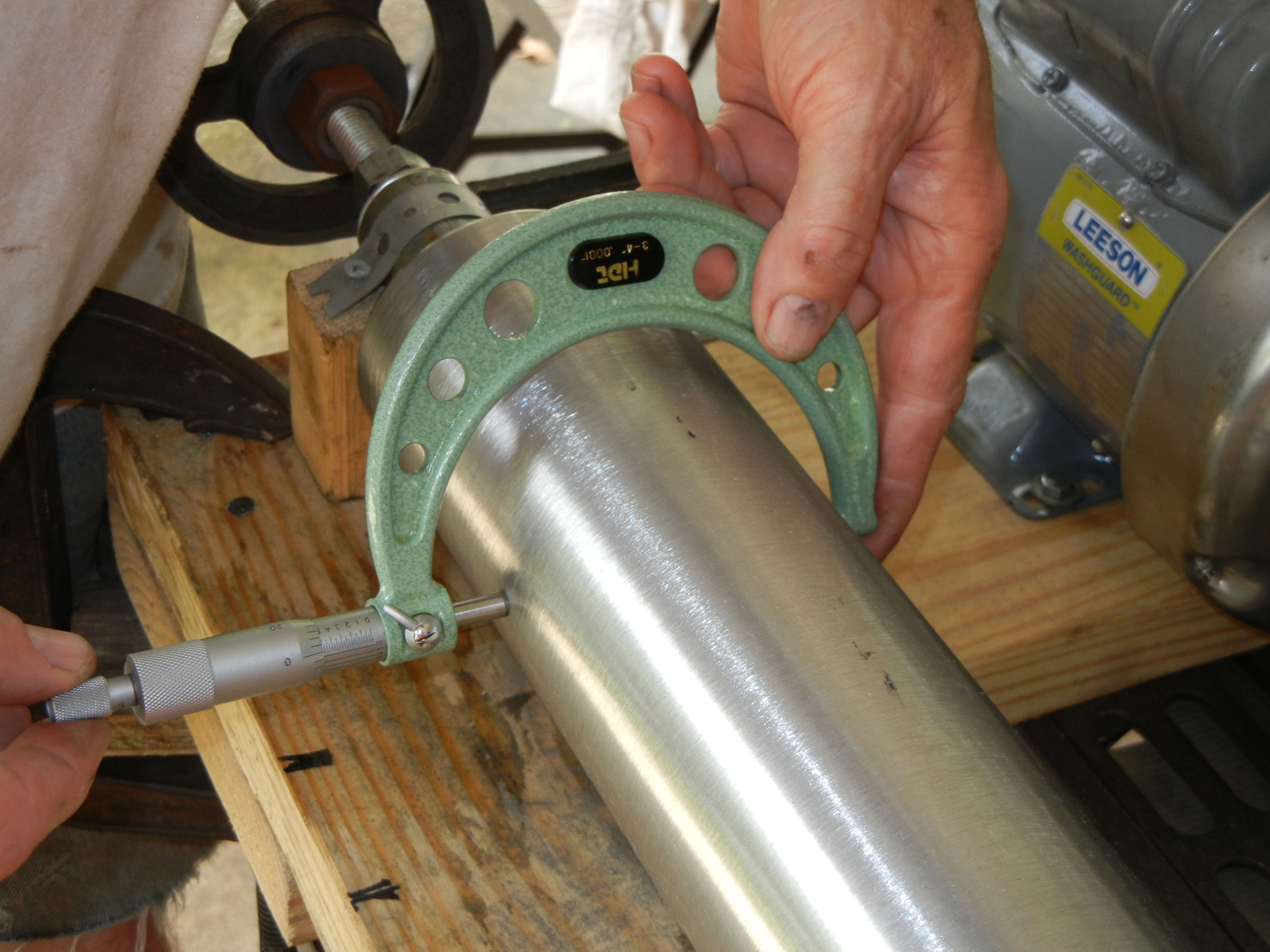
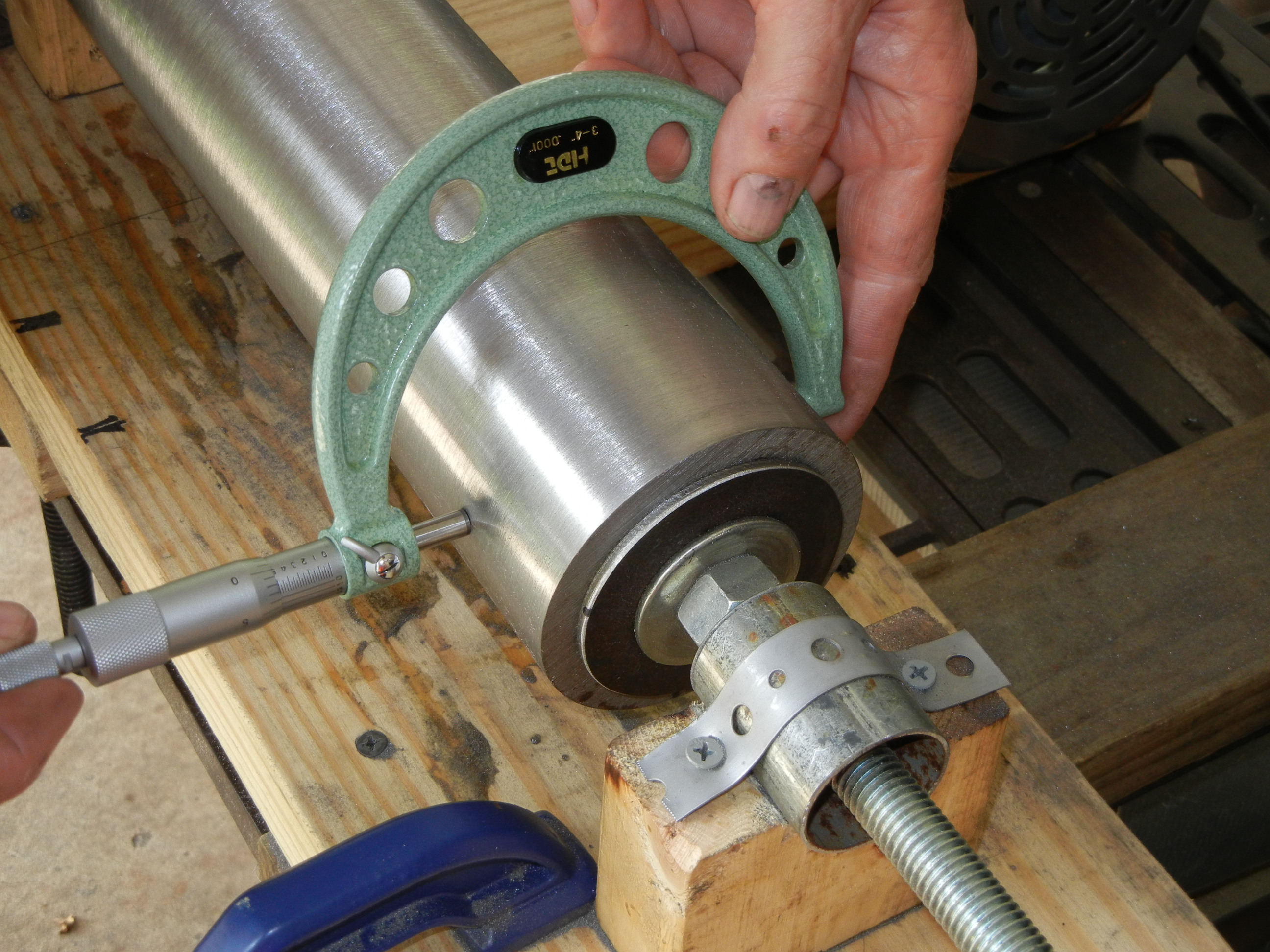
For size references, my China calipers could not measure squarely inside the bore due to the shape of the caliper head, but when using a telescoping gauge and micrometer, the bore did measure 3.4975"
Now knowing the true ID of the Reid C's bores (3.4975"), we carefully studied the supplied installation instructions which states the units are designed for a 0.0025" press fit- no more, no less! This basically equates to a required final tube OD of 3.500". Attention was then turned again to the housing end in which this time we used a telescoping gauge and micrometer to record a more accurate ID of the housing end. We measured 3.496" and then again 90* rotated we read 3.497". Using the micrometer directly on the old axle tube we measured 3.501" and then again 90* rotated we read 3.502". Perhaps the egg shape was a result of the original plug welds or continuous loading of the weight of the vehicle, but either way this proved a 0.005" press fit all the way around. It was decided by us to just make the tube one constant diameter the full length for ease of machining. With a final tube OD of 3.500" there was a press fit of 0.003" to 0.004" since our new tube was not egg shaped (yet).
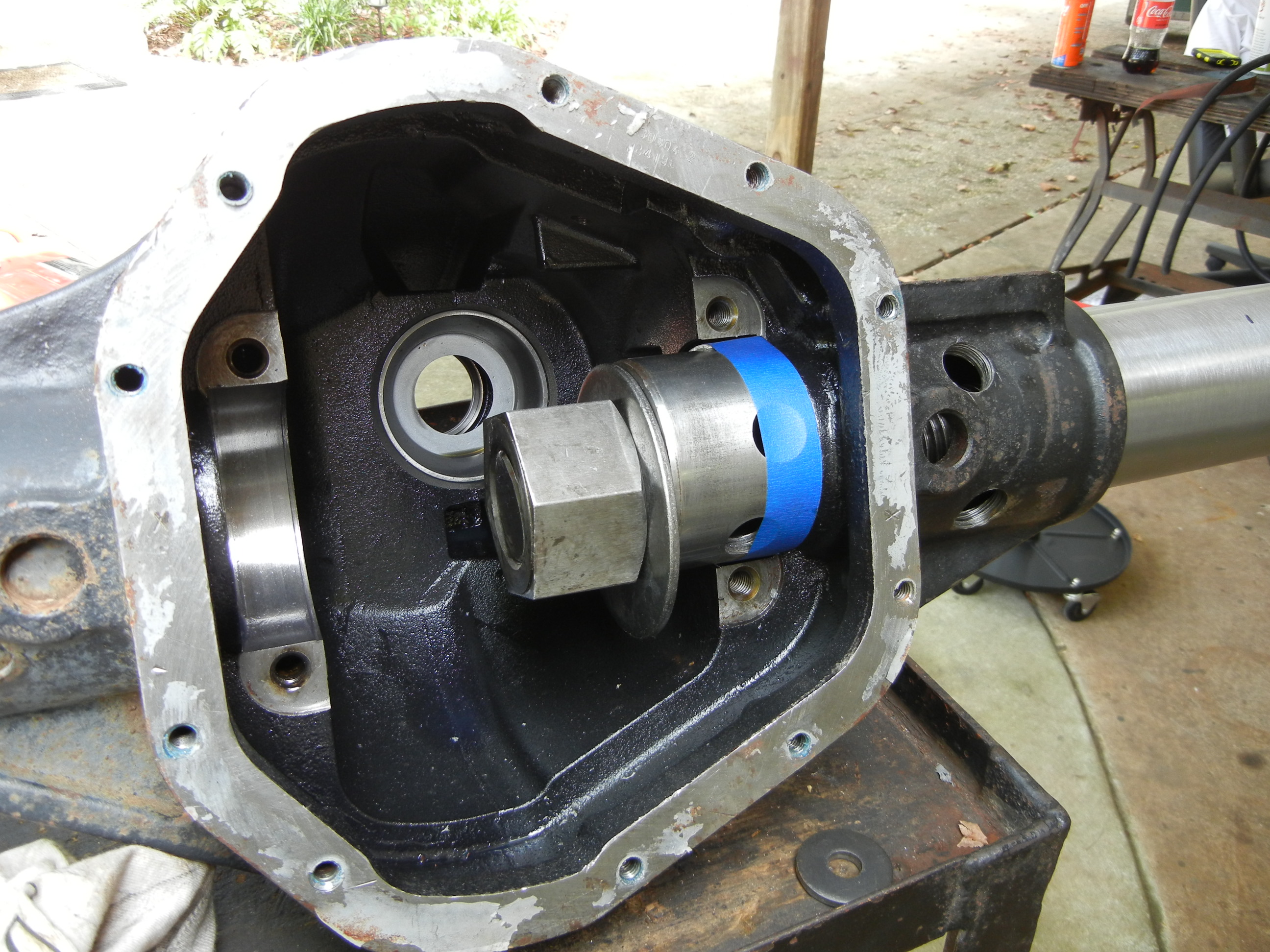
After the tube was finished, it was time to see if it would press into the housing! A few taps of the dead blow to get it started and then mount the threaded rod. Another nut and washer were used on the inside as well as a piece of the original tube for a spacer to rest within the bearing race surface to act as a "pull point". The pipe wrench was used simply to keep the inside nut from spinning. At first the inside washer and nut are shown as sagged, but after the initial torque was applied, we centered the nut and spacer so it could pull squarely against the housing. Then the long cheater pipes came out to play again. When tightening the nut, this will truly test your strength as the cheater bars are almost as large as the new tube is! Not to mention we were wondering if the housing was going to CRACK at any given moment given the extreme forces needed to tighten the nut! The nodular cast iron housing must be stronger than you think!
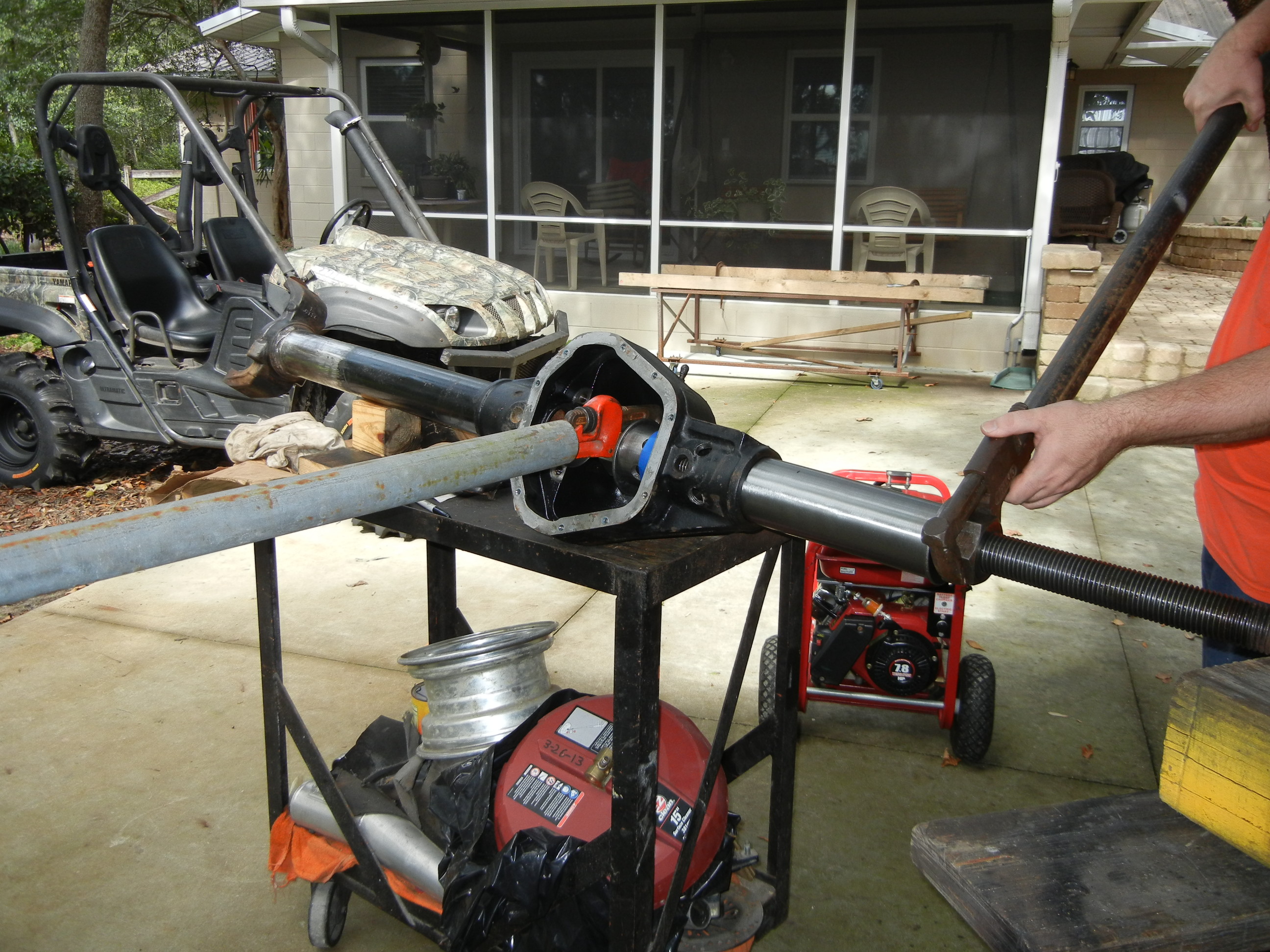
Similar to when the original tube was removed, it was easy to install the tube up to the 3/4 mark. Then it was getting progressively more difficult to turn the wrenches so we placed the unit on saw horses for more stability. Sure enough the tube kept sliding in.

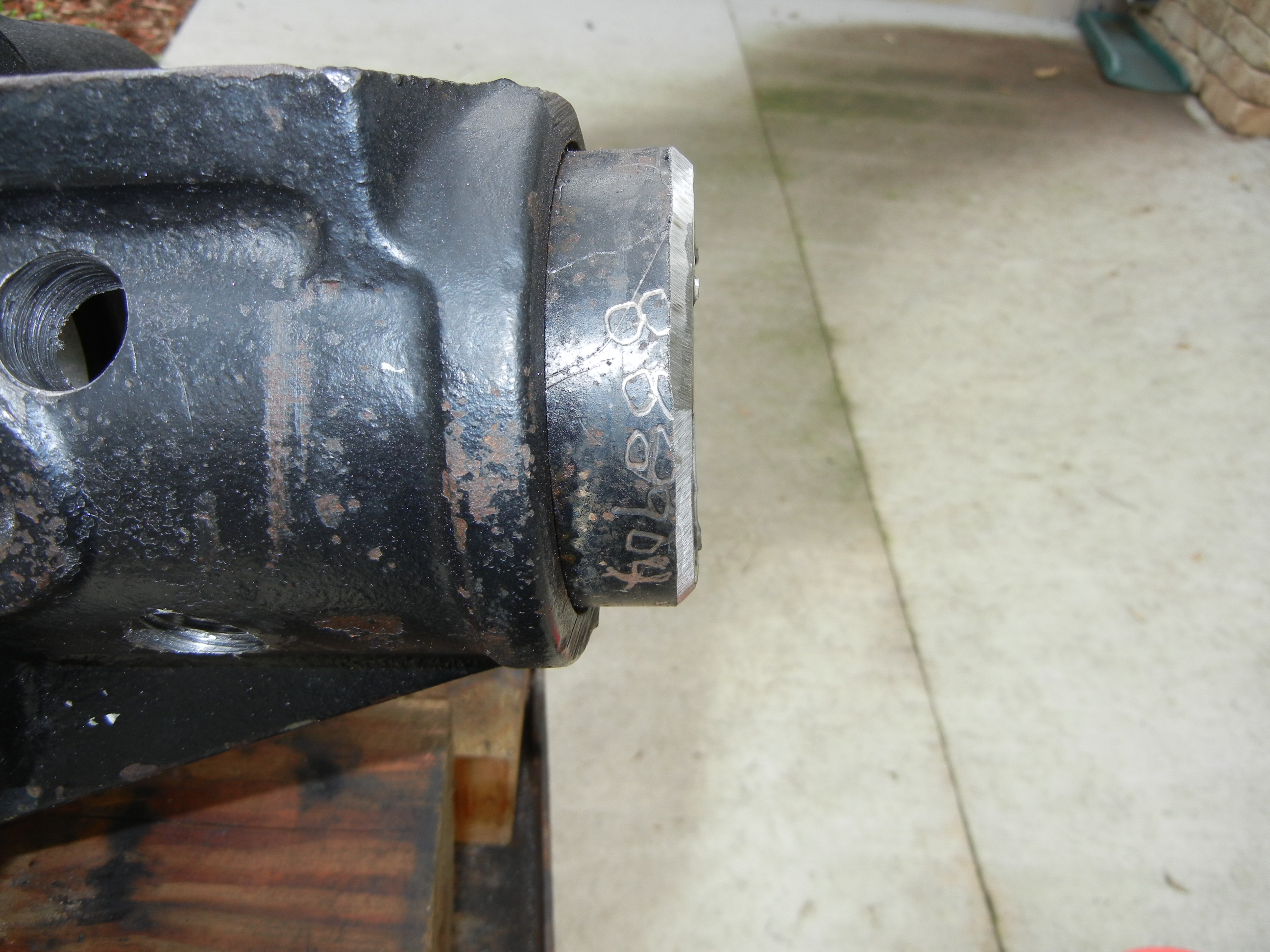
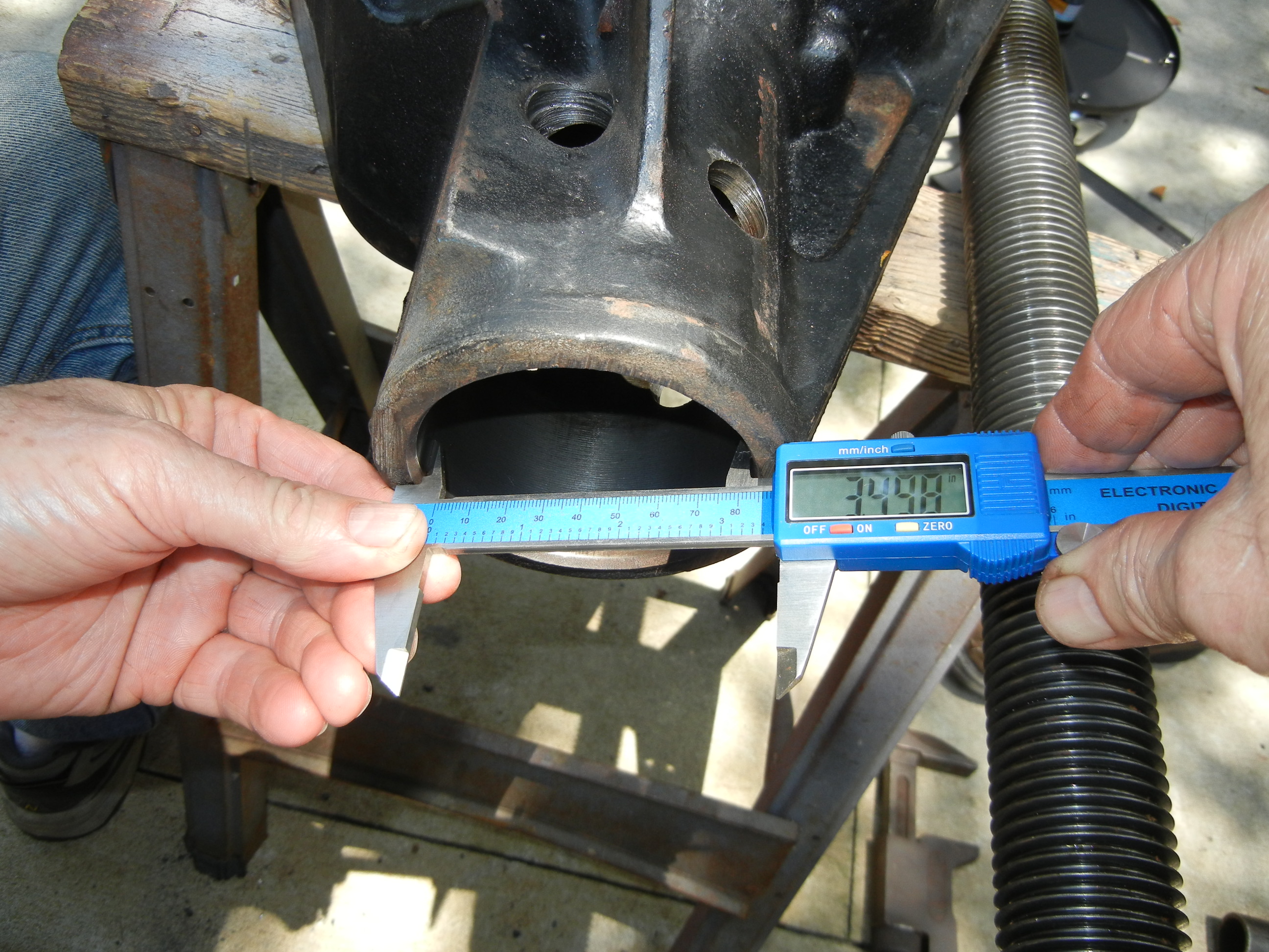
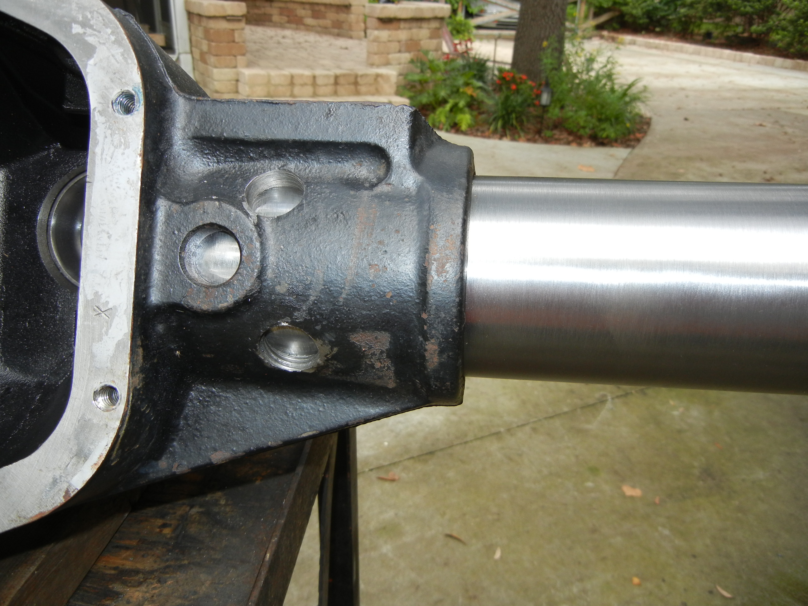
Here is the new tube fully driven home. Just as the original design, we left a gap by not pressing the tube all the way until it bottomed out. Once again you can see no heat was used as it was our intention to install this cold just like the axle manufactures do. All that is left to do now is weld up the plugs and cut off the other ball joint C. The ends of the tubes will be cut to length once we know what this is going in!
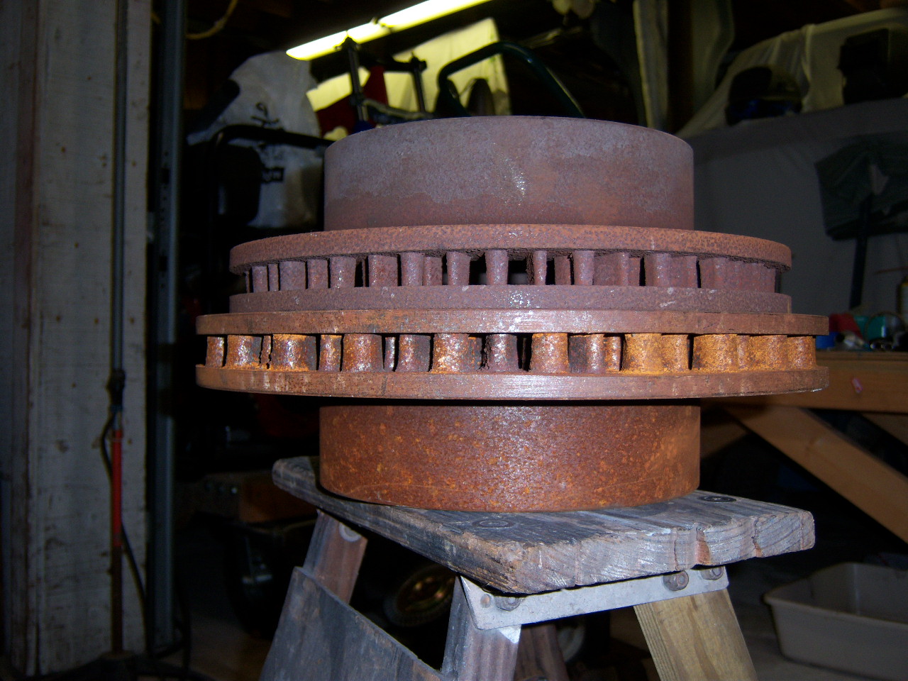
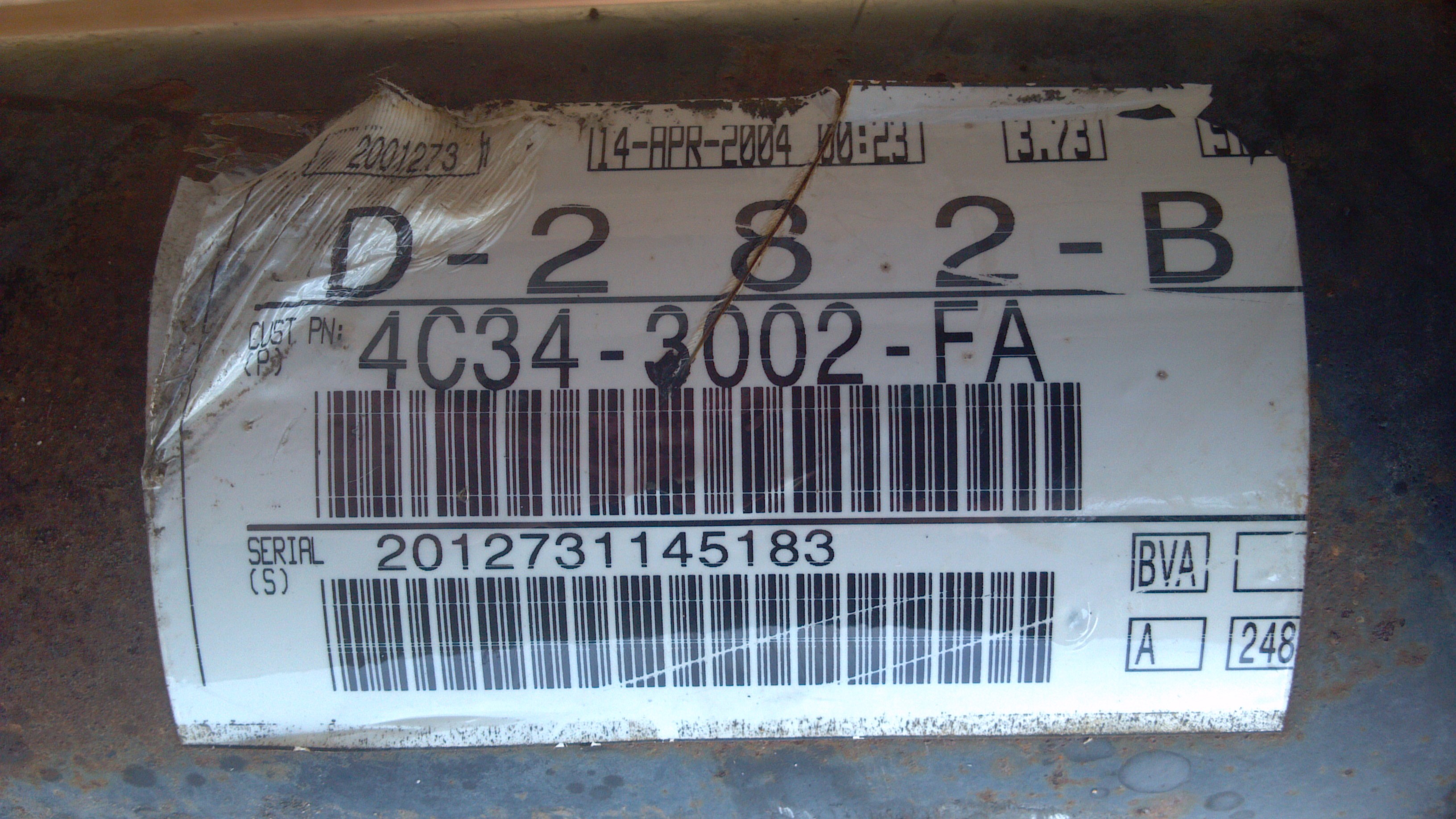
Calculations were done on this axle to see how it compared with the other Dana 60's that have been produced over the years. Knowing there is no possible way to accurately compare multiple axle series with one another, instead we focus on one aspect of each of the axles' common features: the tubes! Assuming the new housing is stronger than the '97 and older style and also assuming the inner C's and outer knuckles have remained the same (ignoring the unit hub fact) the tubes really are the only item left. Luckily they can be treated as a loaded beam in engineering mechanics, but without even looking into that, just comparing the geometry with each other can tell us a lot about the strength of the newer generation axles. The second moment of inertia or also known as the area moment can be used to study the material's resistance to bending all while simply looking solely at the geometric shape of the member. All other elements are removed from the equation such as length, composition, mass, external forces, etc. Below is a chart comparing the three most common sizes of D60 front axle tubes: 2005 and up with 3.75" tube represented by the red line, 1999-2004 Superduty (both 250/350 and 450/550) with 3.5" tube represented by the blue line and the famous 1978-97 with 3.125" tube represented by the magenta line. It is interesting to note the 99-04 250/350 tubes are some metric/import size sitting right at 0.35" thick while the 450/550 tubes are spot on 7/16" or 0.4375" yet unfortunately we do not have an '05-newer axle to determine the tube thickness so I can only guess they are 3/8" thick.
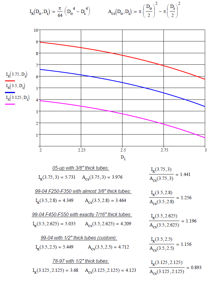
Since the curves are functions of two variables- inner ID and outer OD, we know the OD will remain constant while only the ID will vary depending on the different configurations (250-350/450-550). If the equation is evaluated at the exact ID dimension, we can compare the second moment of inertias with each other (Ix). The total cross sectional area (Acs) can also be determined from simple geometry which will compare the overall unit weight of the material given an equal length piece is compared for all examples. Not surprisingly the 99-04 250-350 tube has the 2nd smallest second moment of inertia and also has the smallest cross sectional area given its think walled design. What is surprising is when the ratio of inertia to area is compared, it has the 2nd highest value of all the axles.
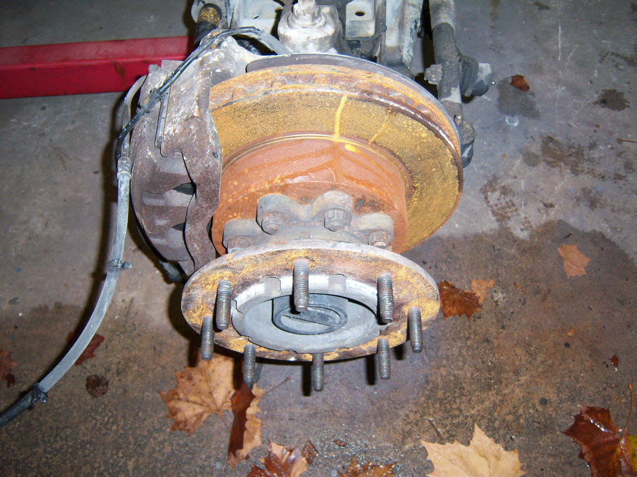
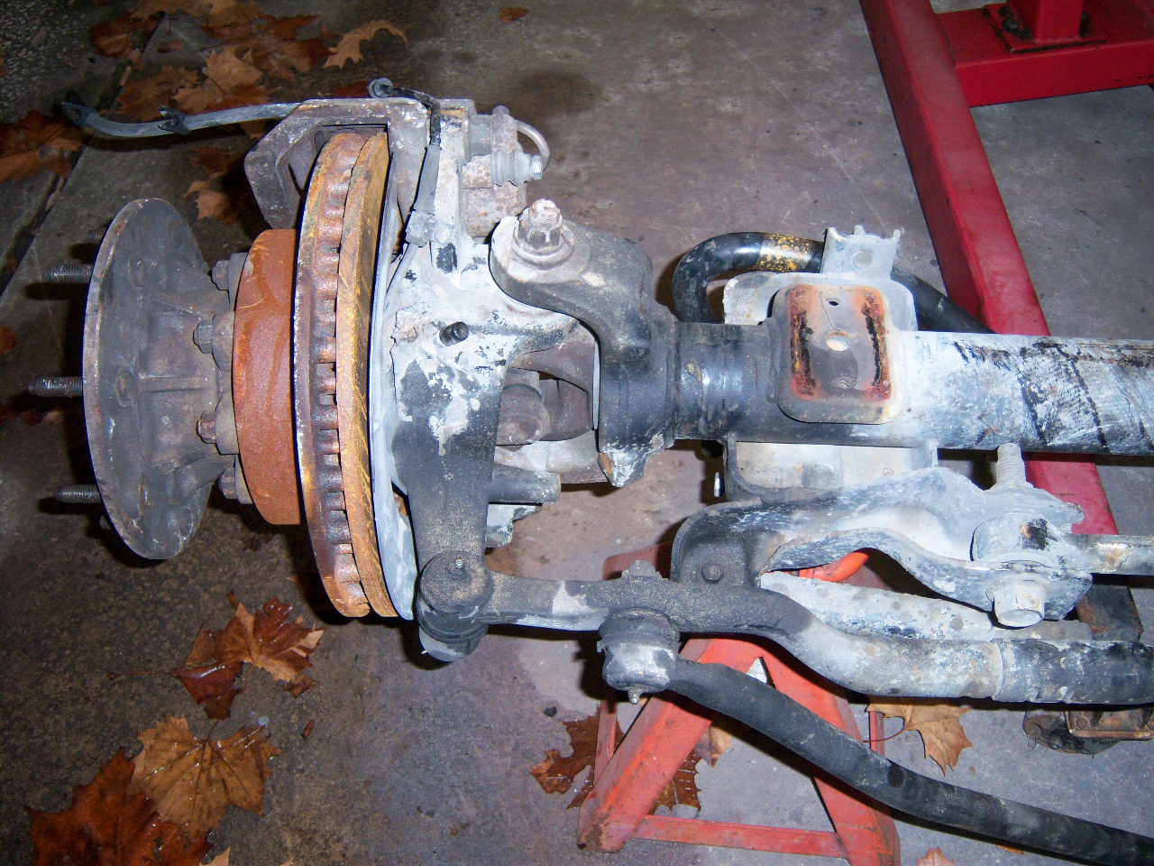
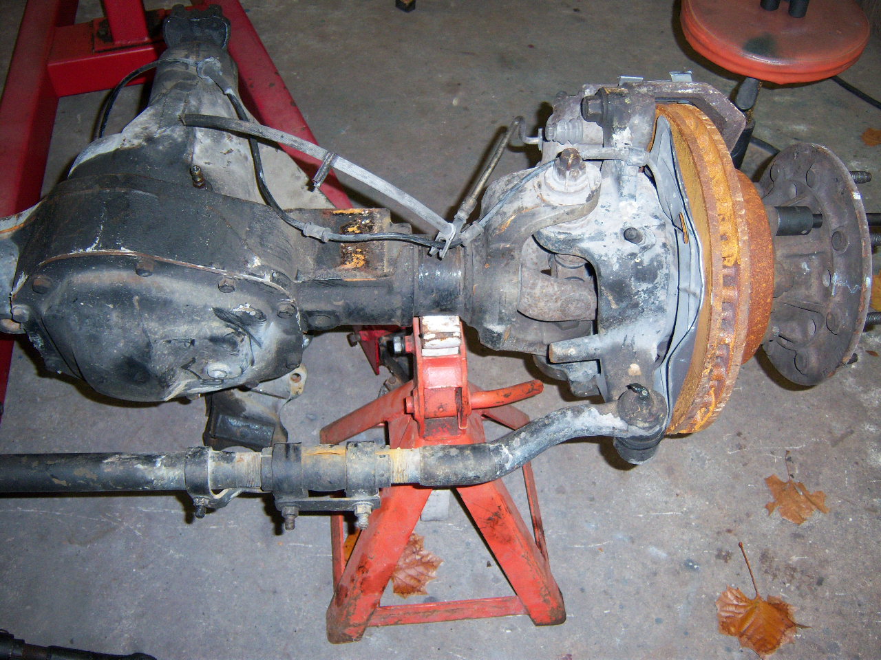
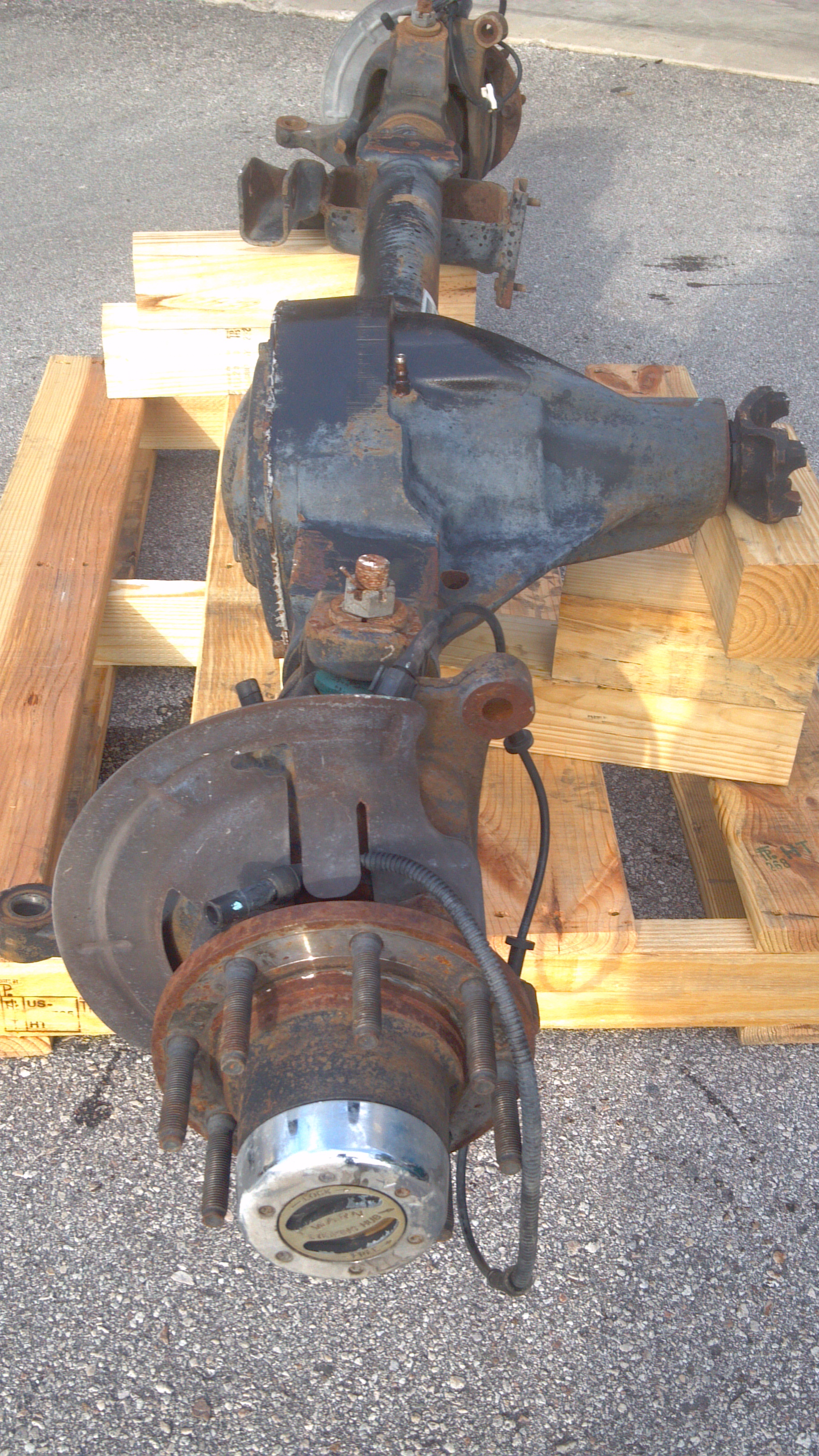
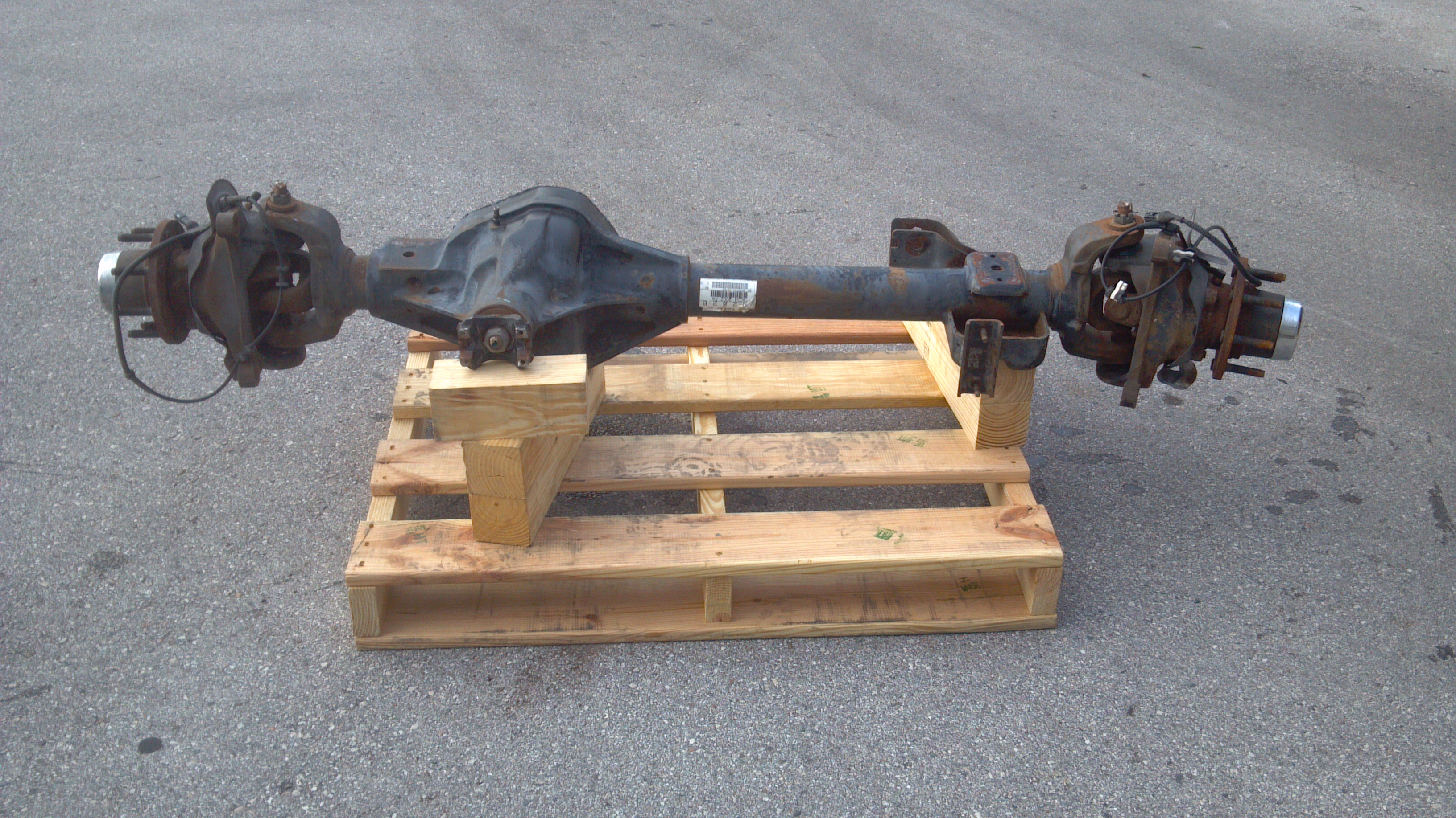
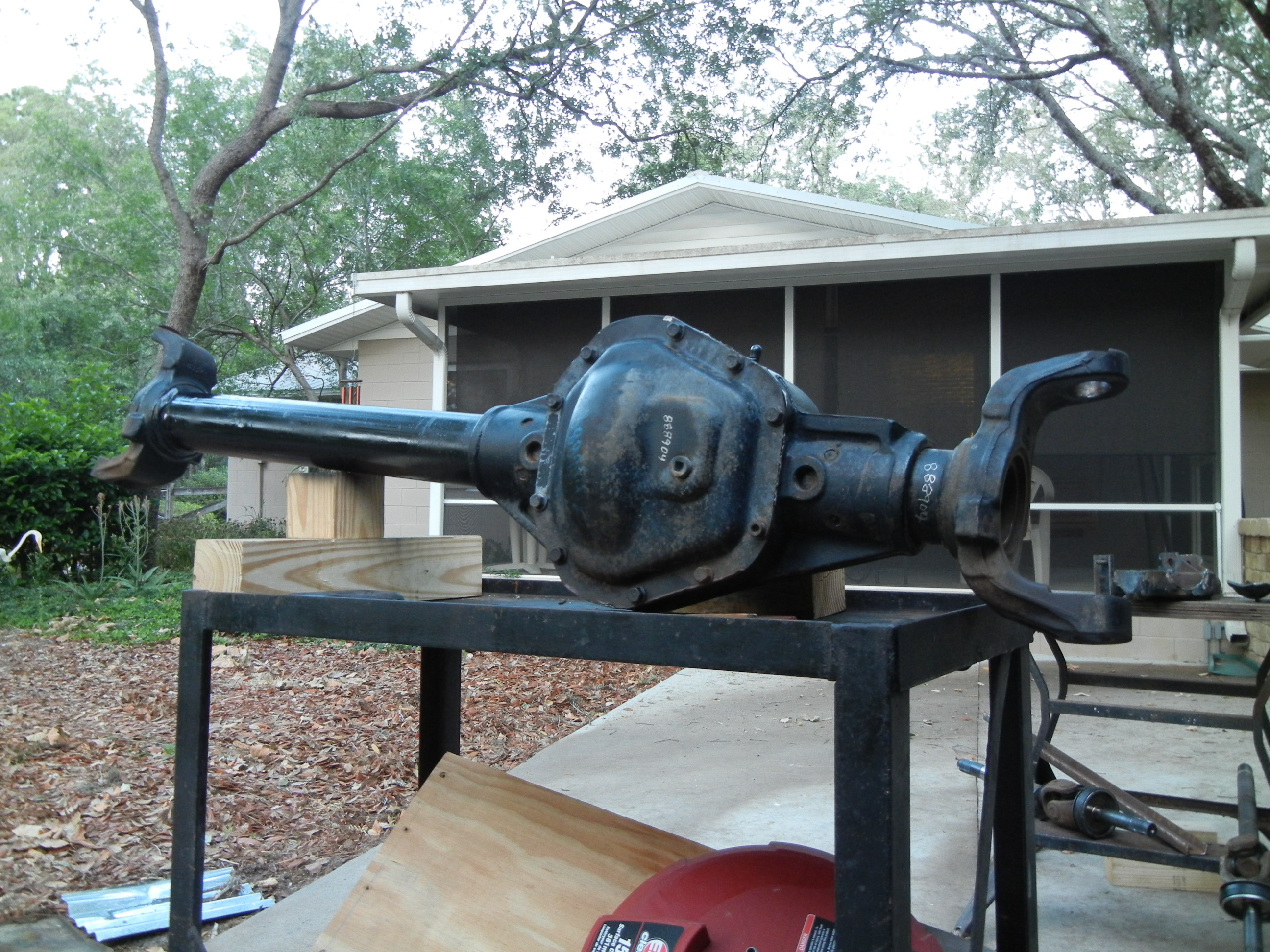
For a comparison with the photos at the beginning of this page, here are some pics of a 2002 F450/550 front D60. Notice the much larger brakes and dually adapters that are used over the 250/350 versions. What may not be as noticeable is the extra track width as evident by the extra inch of tube between the inner C and the spring pad and housing. Therefore the axle shafts are also F450/550 specific.